
CON-110 · Lesson 8 of 12 · 25 min
Formwork, falsework and shoring
Fresh concrete is a heavy fluid that takes the shape of whatever contains it. Formwork is the temporary mould that holds concrete in place until it can support itself, and falsework and shoring are the temporary structures that support formwork, fresh concrete, workers and equipment above the ground. Formwork often accounts for a third or more of the cost of a concrete structure and has a large influence on its schedule, quality and safety; formwork failures, from blowouts of wall forms to collapses of slab shoring, are among the most serious accidents in construction. This lesson explains the purposes of formwork, its components and systems, how fresh concrete pressure is estimated, the loads on shoring, stripping and reshoring, and the safety and regulatory requirements that apply.
Requirements for good formwork
Formwork must be strong enough to carry the pressure and weight of fresh concrete and construction loads without failure; stiff enough that deflection does not distort finished surfaces beyond tolerances; tight enough to prevent loss of paste, which leaves honeycombing and stains; accurate in dimension, line and level; able to produce the specified surface finish, from rough concealed surfaces to architectural finishes; easy and safe to erect, strip and reuse; and economical. Economy comes mainly from reuse, simple repetitive geometry and fast cycles, which is why designers and contractors try to keep column sizes, slab thicknesses and wall heights consistent.
Components and materials
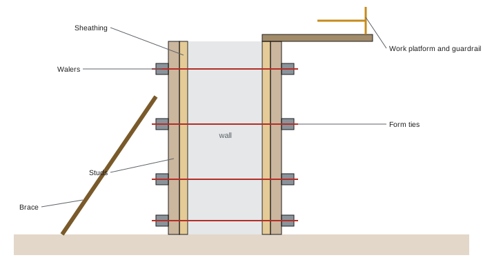
Common formwork materials include plywood and high-density overlay panels for form faces, dimensional lumber and engineered wood joists, aluminium beams and frames, steel panels for repetitive or heavy-duty work, plastic and fibreglass forms for columns and special shapes, and expanded polystyrene in insulated concrete forms that stay in place. Wall forms typically consist of:
- Sheathing: the face in contact with concrete.
- Studs: vertical members supporting the sheathing.
- Walers (wales): horizontal members supporting the studs.
- Form ties: steel ties that pass through the wall and hold the two faces together, resisting concrete pressure; the ends are snapped off or removed after stripping, leaving holes that are patched.
- Bracing and alignment: diagonal braces and strongbacks keep forms plumb and resist wind and impact.
Slab formwork typically consists of sheathing on joists, joists on stringers or beams, and stringers on shores or scaffold frames that carry loads to the floor or ground below. Form release agents are applied to sheathing to prevent bond and ease stripping. Chamfer strips at corners reduce chipping, and embedded items such as sleeves, inserts, anchor plates and conduit boxes are fixed to the forms before concrete is placed.
Formwork systems
Beyond job-built wood forms, contractors use engineered systems:
- Modular panel systems: steel or aluminium framed panels clipped together for walls and columns, fast and reusable.
- Gang forms: large assemblies of panels moved by crane as a unit.
- Climbing and self-climbing forms: wall forms that climb up cores of tall buildings using hydraulic jacks, anchored to previously cast concrete.
- Slipforms: forms moved continuously upward while concrete is placed, for silos, cores and towers.
- Flying forms (table forms): large slab form assemblies moved floor to floor by crane.
- Drop-head and panel slab systems: systems in which panels can be stripped early while props stay in place.
- Tunnel forms for repetitive cellular buildings, column forms in steel, fibreglass or cardboard tubes, and stay-in-place forms such as metal deck, precast planks and insulated concrete forms.
The choice depends on the geometry, number of reuses, crane availability, schedule and labour costs.
Pressure of fresh concrete on vertical forms
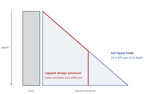
Fresh concrete behaves like a fluid when first placed. If it remained fully liquid, the pressure at any depth would equal the hydrostatic pressure of a fluid with the density of concrete:
where \(\rho\) is the density of concrete (about 2,400 kg/m³), \(g\) is gravitational acceleration (9.81 m/s²) and \(h\) is the depth of fluid concrete. This gives about 23.5 kPa per metre of depth, or about 150 psf per foot in imperial units, since normal-weight concrete weighs about 150 lb/ft³. In practice, concrete begins to stiffen as it sets, so the pressure stops increasing once the concrete below has stiffened; the maximum lateral pressure therefore depends on the rate of placement, the concrete temperature, the setting characteristics of the mix, the method of consolidation and the height of the form. Fast placement, cold temperatures, retarders, SCMs and self-consolidating concrete all increase pressure, and designers of high forms filled quickly often assume the full liquid head.
Worked problem
Full liquid head pressure on a wall form
A wall form is 3.6 m (about 11.8 ft) high and will be filled in one quick placement with self-consolidating concrete, so the designer assumes full liquid head. What is the maximum pressure at the bottom and the total force per metre of wall on one face?
Show solution
- Pressure at the bottom: 2,400 × 9.81 × 3.6 ≈ 84,800 Pa ≈ 85 kPa.
- In imperial units: 150 psf/ft × 11.8 ft ≈ 1,770 psf.
- Pressure varies linearly from zero at the top to 85 kPa at the bottom, so the resultant force per metre of wall is the area of the triangle: ½ × 85 × 3.6 ≈ 153 kN/m.
- The resultant acts at one third of the height from the bottom, so the lower ties and walers carry the most load; form tie spacing is usually closer near the bottom.
Answer: About 85 kPa (1,770 psf) at the bottom and about 153 kN per metre of wall on each face, mostly carried by the lower ties.
In Canada, CSA S269.3 covers the design and construction of concrete formwork, and CSA S269.1 covers falsework and shoring; provincial occupational health and safety regulations, such as Ontario Regulation 213/91, require formwork and falsework for many structures to be designed by a professional engineer, built according to the drawings and inspected before concrete is placed.
Loads on slab formwork and shoring
Slab forms and shoring carry vertical loads: the dead load of fresh concrete and reinforcing, the self-weight of the forms, and construction live loads from workers, equipment, concrete buggies and stored materials, plus impact from dumping concrete. A 200 mm (8 in) slab weighs about 0.2 × 23.5 ≈ 4.7 kPa (about 100 psf), and design standards typically add a minimum construction live load of about 2.4 kPa (50 psf), with higher values where motorized carts are used. Shoring also needs lateral bracing for wind, uneven placement and accidental impact, and its foundations, whether mud sills on soil or slabs below, must carry the concentrated loads. Many shoring collapses start with inadequate bracing, settlement of mud sills on wet ground, missing or loosened components, or placement sequences that overload one area.
Stripping, reshoring and backshoring
Forms can be removed once concrete has gained enough strength to carry its own weight and any construction loads without damage or excessive deflection. Vertical forms for walls and columns that carry no load may be stripped after a day or two, provided the concrete is strong enough not to be damaged and curing continues; soffit forms and shores under slabs and beams must stay until the concrete reaches a specified strength, often a percentage of \(f'_c\) determined from field-cured cylinders or maturity data (Lesson 12). Stripping by calendar alone is risky, especially in cold weather when strength gain slows.
In multi-storey buildings, freshly cast floors cannot yet carry the loads of the floors above, so reshores are installed after stripping to transfer loads down through several floors to the ground or to mature slabs. Backshoring is similar but done one bay at a time without fully removing support. The number of levels of shores and reshores, and the sequence of removal, is designed by the formwork engineer and must be followed exactly.
| Element | Typical criterion for removal | Notes |
|---|---|---|
| Wall and column sides | Concrete can resist damage; often 12 to 48 h | Continue curing after stripping |
| Beam sides | Similar to walls | Shores under soffits remain |
| Slab and beam soffits | Specified strength, often 70 % to 75 % of f'c | Confirm with field-cured cylinders or maturity |
| Reshores | Per formwork engineer's sequence | Usually several floors |
| Post-tensioned slabs | After stressing, per engineer | Never strip before stressing |
Formwork safety
Key safety requirements include designed and engineered drawings for formwork and shoring where regulations require them; inspection of formwork before and during concrete placement by a competent person or engineer; secure access, guardrails and fall protection at form edges and on decks; safe crane rigging for gang and flying forms, with rigging points designed for lifting; protection against impalement on rebar dowels with caps or covers; control of the placement rate and sequence to match the design assumptions; a watcher below forms during placement to look for movement, bulging or leaking where safe; and keeping people out from under shores and slabs during placement. If forms begin to move, placement must stop immediately and workers must be cleared from the area.
Formwork and quality
Formwork determines the quality of exposed surfaces and dimensions. Problems that originate in formwork include bulges and misalignment from inadequate ties or bracing; honeycombing and sand streaks from paste leaking at joints; surface staining from poor release agents or contaminated plywood; deflection of slab soffits; and incorrect positions of embedded items. Tolerances for formed surfaces, such as plumb, line and level, are set in standards and specifications, and architectural concrete may require mock-ups to establish acceptable finishes. Camber is sometimes built into slab and beam forms to compensate for expected deflection.
Planning formwork for productivity
Because formwork is such a large part of the cost of concrete work, contractors plan it carefully. A formwork plan divides the structure into pours, decides how many sets of forms are needed and how they will cycle from one pour to the next, and identifies the cranes, hoists and labour required. For a multi-storey building, the goal is often a repeating floor cycle, for example a four- or five-day cycle in which columns and walls are formed and poured, the slab formwork is flown or moved, reinforcement and services are installed, the slab is poured and the forms are stripped and moved up. Achieving a steady cycle depends on concrete reaching stripping strength on time, which may require high early strength mixes, heated enclosures in winter or maturity monitoring.
Repetition is the key to economy. Forms that can be reused many times without modification reduce material and labour costs, while every change in column size, slab thickness or wall height requires new forms or adjustments. Contractors with early involvement in design, for example under design-build or construction management delivery, often suggest changes that simplify formwork, such as consistent column sizes over several floors or flat plate slabs without drop beams.
Inspection before and during placement
Formwork inspection before placement checks that the forms match the dimensions, lines and levels on the drawings; that ties, walers and bracing are installed as designed; that shores are plumb, properly spaced, sitting on adequate sills and braced; that forms are clean and oiled; that embedded items are secured; and that safe access and edge protection are in place. Where the regulation or the specification requires it, a professional engineer reviews the falsework and issues a written confirmation before concrete is placed.
During placement, a carpenter or form watcher monitors the forms, checking for movement, bulging, leaking, settlement of shores or loosening of wedges and clamps. The placement crew follows the planned sequence and rate, for example placing slab concrete symmetrically so that shores are not overloaded on one side, and avoiding heaps of concrete that create concentrated loads. If any warning signs appear, placement stops while the problem is assessed. Many formwork failures happen during placement, when loads are greatest and the concrete is still fluid.
Common mistakes
MistakePlacing concrete faster than the form design assumes.
InsteadControl the rate of placement to match the design.
MistakeSetting shores on soft, wet ground without proper sills.
InsteadUse designed mud sills on prepared ground.
MistakeStripping slab forms by calendar in cold weather.
InsteadStrip only when strength is confirmed.
MistakeRemoving reshores out of sequence.
InsteadFollow the formwork engineer's sequence exactly.
MistakeContinuing a pour when forms start to move.
InsteadStop placement and clear the area.
Summary and key terms
- Formwork shapes concrete; falsework and shoring support it above ground.
- Good formwork is strong, stiff, tight, accurate, safe and economical.
- Wall forms use sheathing, studs, walers, ties and bracing.
- Full liquid head pressure is about 23.5 kPa per metre (150 psf per foot).
- Rate of placement, temperature and mix affect form pressure.
- Strip soffits only when the concrete has reached the required strength; follow reshoring designs.
- Formwork safety depends on engineering, inspection, controlled placement and fall protection.
- Formwork
- Temporary mould for fresh concrete.
- Falsework
- Temporary structure supporting formwork above ground.
- Shore
- Vertical support under slab or beam forms.
- Form tie
- Steel tie holding wall form faces together.
- Waler
- Horizontal member supporting form studs.
- Liquid head
- Pressure of concrete assumed fully fluid.
- Reshoring
- Temporary supports installed after stripping to carry loads.
- Release agent
- Coating preventing concrete from bonding to forms.
- Flying form
- Large slab form moved by crane floor to floor.
- Slipform
- Form moved continuously upward during placement.
Practice problems
Work each problem on paper first, then reveal the answer to check.
What is the purpose of formwork?
Show answer
To hold fresh concrete in shape until it can support itself.
Liquid head pressure at 2 m depth?
Show answer
About 47 kPa.
Liquid head pressure at 8 ft depth?
Show answer
About 1,200 psf.
Name two factors that increase form pressure.
Show answer
Fast placement, cold weather, retarders, SCC.
What do form ties resist?
Show answer
Lateral pressure of fresh concrete.
Weight of a 250 mm slab?
Show answer
About 5.9 kPa.
Why are reshores used?
Show answer
To carry loads of upper floors through young slabs.
What determines when slab soffits are stripped?
Show answer
Confirmed concrete strength per specification.
What should happen if forms begin to move?
Show answer
Stop placement and clear workers.
Name two engineered formwork systems.
Show answer
Gang forms, climbing forms, slipforms, flying forms.
Lesson quiz · 5 questions
Score 60% or more to complete this lesson.
Create a free account to save your progress, take quizzes and earn a certificate.