
CON-120 · Lesson 2 of 12 · 28 min
Lines, lettering, symbols and abbreviations
If drawings are a language, lines are its alphabet. Every line on a construction drawing has a weight, a pattern and a meaning: a thick continuous line might be a wall cut through on a plan, a thin dashed line an object hidden above or below, a long chain of dashes and dots a centre line or grid line. Symbols and abbreviations then add vocabulary, packing a great deal of information into a small space. This lesson teaches the alphabet and the common vocabulary: line types and weights, lettering and notes, material hatches, reference symbols, tags, and the abbreviations that fill every set. Each set has a legend that defines its own symbols, and the legend always governs, but most sets follow similar conventions, so learning the common ones lets you read quickly and spot when a set does something unusual.
Line weights
Line weight is the thickness of a line. Drawings use a hierarchy of weights so that the most important information stands out:
- Heavy (thick) lines show objects cut by the plane of a plan or section, such as walls, columns and slabs in section, and the outline of the building on a site plan.
- Medium lines show objects seen beyond the cut but not cut, such as the edges of countertops, steps or a window sill seen in elevation.
- Light (thin) lines show dimensions, leaders, hatching, grid lines and other annotation, and minor surface features.
On a well-drawn floor plan, a quick glance shows the walls in bold, the furniture and fixtures lighter and the dimensions lightest of all. This hierarchy makes plans readable at a glance. When drawings are printed poorly, reduced too far or viewed on a small screen, line weights can be lost, which is one reason to view important sheets at full size or zoom in on the PDF.
Line types
Line type, or pattern, tells you what kind of object a line represents. The most common types are:
| Line type | Appearance | Typical meaning |
|---|---|---|
| Object (visible) | Continuous | Visible edges and outlines of objects |
| Hidden | Short dashes | Edges hidden behind or below other objects, such as footings under a slab |
| Overhead | Long dashes or dash-dot | Objects above the cut plane, such as a roof overhang, bulkhead or skylight |
| Centre line | Long dash, short dash | Centres of symmetrical objects, columns, pipes or openings |
| Grid line | Long dash, short dash, with bubble | Reference grid for locating structure and walls |
| Property line | Long dash, two short dashes | Legal boundary of a site |
| Dimension and extension lines | Thin continuous with ticks or arrows | Measurements between points |
| Break line | Thin line with a zigzag | An object shortened or cut off to save space |
| Section cut line | Heavy dash-dot with end symbols | Location and direction of a section view |
| Demolition | Dashed, often with a note | Existing work to be removed |
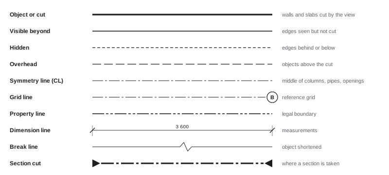
Some lines change meaning by discipline. On civil drawings, dashed lines with letters, such as a line marked "W" or "SAN", show buried water mains or sanitary sewers; on electrical drawings, lines between symbols show circuits; on mechanical drawings, single lines can represent pipes and double lines ductwork. The discipline's legend sheet explains these.
Existing, new and demolished work
On renovation and addition projects, drawings must distinguish existing construction to remain, existing construction to be removed and new work. Common conventions are:
- Existing to remain: lighter or grey lines, sometimes screened (shown at reduced intensity).
- Existing to be removed: dashed lines, often on separate demolition plans, with demolition notes or keynotes.
- New work: bold, solid lines, often with a hatch or fill for new walls.
Many sets include separate demolition plans before the new construction plans. Reading both together is essential, because the demolition plan tells you what must go before the new work can start, and items shown dashed on a demolition plan are work in the contract, with real cost and real hazards such as asbestos or structural support.
Lettering, notes and keynotes
Text on drawings is kept short and consistent. Most drawings use upper-case sans-serif lettering, whether hand-drawn in the past or generated by CAD today, because it remains legible when reduced. Text comes in several forms:
- View titles: the name of each view with its number and scale, such as "2 WALL SECTION, SCALE 1:20".
- Labels and leaders: short text with a thin line (the leader) pointing to the object it names.
- General notes: numbered notes that apply to the whole sheet or the whole discipline, often placed on the first sheet of each discipline. Structural general notes, for example, give design loads, material strengths and standards.
- Sheet notes: notes that apply only to the sheet on which they appear.
- Keynotes: numbered or coded tags on the drawing that refer to a list of notes on the same sheet, keeping the drawing uncluttered. Some offices tie keynotes to specification section numbers, so a keynote such as 09 21 16.A refers to a gypsum board item in that specification section.
General notes are easy to skip and costly to miss. They often contain requirements that appear nowhere else on the drawings, such as "Provide blocking for all wall-mounted equipment", "All dimensions are to face of stud unless noted otherwise" or "Contractor to verify all existing conditions before starting work".
Material indications and hatches
In sections and plans, the cut surfaces of materials are filled with hatch patterns that indicate the material. A few patterns are almost universal:
- Concrete: a random pattern of dots and small triangles representing aggregate.
- Masonry (brick or block): diagonal lines, with concrete block often drawn as diagonal lines with a different spacing or cross-hatching.
- Earth: a pattern of short diagonal strokes, sometimes with dots, below grade.
- Gravel or granular fill: small circles or stones.
- Wood: an X through dimensional lumber cut in section, or a grain pattern for finished wood; plywood shown with layered lines.
- Steel: solid fill or close diagonal lines for small sections.
- Insulation: a loopy wavy line for batt insulation and a cross-hatched or diagonal pattern for rigid insulation.
- Gypsum board, plaster and finishes: often too thin to hatch and drawn as single or double lines with labels.
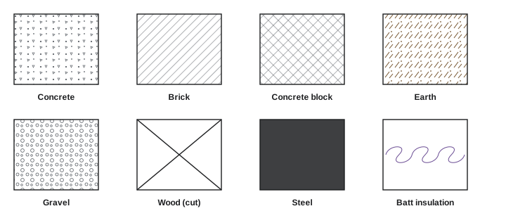
Hatches only show the general material. The exact product, strength and grade come from labels, notes and the specifications. A concrete hatch does not tell you the concrete strength; the structural general notes or the specifications do.
Reference symbols
Reference symbols connect views across the set (Lesson 1). Their exact shapes vary by office, but the common ones are:
- Section symbol: a circle divided by a horizontal line, with the view number above and the sheet number below, attached to a cut line, with an arrow or solid triangle showing the direction of view.
- Detail callout: a circle or rounded boundary drawn around the area to be enlarged, connected to a bubble with the detail number and sheet number.
- Elevation marker: a circle or square with one to four arrows or triangles, each with a view number, showing the directions of interior or exterior elevations.
- View title: placed under each view, with a bubble repeating the view number and the sheet from which it is referenced, plus the title and scale.
- Grid bubble: a circle at the end of each grid line containing a letter or number.
- Match line: a heavy line with a label where a large plan continues on another sheet, such as "Match line, see A-103".
- North arrow: shows plan north, sometimes alongside true north if the building is rotated from the compass.
- Spot elevation: a symbol, often a small cross or target with a number, giving the height of a point (Lessons 3 and 5).
- Revision cloud and delta: a scalloped cloud drawn around changed work with a triangle containing the revision number (Lesson 11).
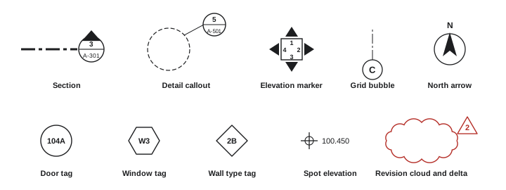
Tags
Tags identify individual items and link them to schedules or legends. Most sets use a different shape for each kind of tag so they are easy to tell apart, for example:
- Door tags: a circle or ellipse with the door number, often matching the room number, such as 104A for the first door into room 104.
- Window tags: a hexagon or diamond with a window type, such as W3.
- Wall or partition type tags: a diamond, rectangle or flag with a code that refers to a wall type legend showing its construction, height and fire rating.
- Room tags: a rectangle with the room name and number, sometimes with the finish code or area.
- Equipment tags: a rectangle or circle with an equipment code, such as AHU-1 for an air handling unit or P-2 for a pump, referring to an equipment schedule.
- Fixture tags: letters or numbers beside plumbing or lighting fixtures, such as WC-1 for a water closet type or L4 for a light fixture type.
Tags are powerful because they keep drawings uncluttered: instead of writing the full construction of every wall, the drawing shows a small tag and the legend shows the construction once. The price of that efficiency is that you must look up every tag. A wall tag that reads 2B might mean a one-hour fire-rated assembly to the underside of the deck above, which is very different from the non-rated partition to the ceiling beside it.
Abbreviations
Drawings use abbreviations heavily. Every set should include an abbreviations list, and you should check it rather than guess, because abbreviations differ between offices and disciplines. Some are nearly universal:
| Abbreviation | Meaning | Abbreviation | Meaning |
|---|---|---|---|
| AFF | Above finished floor | TYP | Typical |
| B/O or U/S | Bottom of, underside of | T/O | Top of |
| CL or ℄ | Centre line | EL or ELEV | Elevation |
| CONC | Concrete | GYP BD or GWB | Gypsum board |
| DIA or Ø | Diameter | O.C. | On centre |
| EQ | Equal | NIC | Not in contract |
| EXIST or (E) | Existing | NTS | Not to scale |
| FD | Floor drain | SIM | Similar |
| FFE or FFL | Finished floor elevation or level | UNO or UON | Unless noted otherwise |
| HM | Hollow metal | VIF | Verify in field |
A few abbreviations deserve special attention because they shift responsibility or scope:
- TYP means the item shown applies everywhere the same condition occurs, even where it is not drawn. One typical detail might govern hundreds of locations.
- SIM means similar: the condition is like the one shown, but not identical, so you must work out the differences, and ask if they are unclear.
- UNO or UON means the note applies unless the drawings say otherwise somewhere else, so you must look for the exceptions.
- NIC means not in contract: the item is shown for coordination but is provided by others, such as the owner or another contractor.
- VIF means verify in field: the dimension or condition must be confirmed on site before work proceeds, and the contractor carries that responsibility.
- NTS means not to scale: never scale the view.
Worked problem
Decoding a dense note
A structural detail contains this note beside a steel beam: "W310×39 T/O STL EL 103.450 UNO. PROVIDE L102×102×9.5 CONT. TYP. SEE S-501/7 FOR SIM." (A US set might read "W12×26 T/O STL EL 112'-4" UNO. PROVIDE L4×4×3/8 CONT. TYP. SEE S-501/7 FOR SIM.") What does it tell you?
Show solution
- W310×39 (or W12×26) names the steel beam: a wide-flange section roughly 310 mm (12 in) deep, with a mass of 39 kg per metre (or a weight of 26 lb per foot). Lesson 7 explains steel designations.
- T/O STL EL 103.450 (or 112'-4") gives the elevation of the top of the steel, measured from the project datum (Lesson 3).
- UNO means this elevation applies unless another elevation is noted somewhere on the drawings for this beam.
- PROVIDE L102×102×9.5 CONT. (or L4×4×3/8) calls for a continuous equal-leg steel angle, 102 mm (4 in) legs, 9.5 mm (3/8 in) thick.
- TYP means the angle is provided at every similar location, not only where drawn.
- SEE S-501/7 FOR SIM. points to detail 7 on sheet S-501 for a similar condition, which you should compare.
Answer: A wide-flange beam with its top at the stated elevation unless noted otherwise, with a continuous steel angle at this and all similar locations, and a similar condition shown in detail 7 on S-501.
Legends and the general sheets
The front of each set, and the first sheet of each discipline, normally contain legends: tables defining the symbols, line types, hatches and abbreviations used. Electrical and mechanical legends are especially long, because those drawings rely heavily on symbols. A set may contain several legends, one per discipline, and they may contradict each other: a circle with a letter might be a door tag on architectural sheets and a light fixture on electrical sheets. Always read each discipline's legend before reading its plans.
Some Canadian sets are bilingual, particularly federal projects and projects in Quebec, New Brunswick and Ottawa, with English and French notes, titles and abbreviations. Projects in Quebec are normally documented in French under the Charter of the French Language, so readers may meet French abbreviations such as BÉT (béton, concrete), TYP (typique) and N.A.É. (non à l'échelle, not to scale).
Dimensions as symbols
Dimensions are themselves a kind of symbol, drawn with thin dimension lines, extension lines that run from the object to the dimension line, and terminators such as arrowheads, ticks (short diagonal slashes, the usual choice on architectural drawings) or dots. The number written on the dimension line is the figured dimension. Lesson 3 explains how to read dimension strings and calculate missing dimensions; for now, notice that a dimension string usually runs between specific reference points, such as a grid line, the face of a stud, the centre line of an opening or the face of concrete. The reference point is part of the information: a dimension "to face of stud" and one "to face of finish" differ by the thickness of the gypsum board.
Reading conventions as a professional
Experienced readers combine these conventions into a fast scanning technique. On a plan, they first see the heavy lines (walls and structure), then read the grid and overall dimensions, then the tags and room names, then the notes and keynotes, and finally follow references to sections and details. They look for anything that breaks the pattern: a wall with a different hatch, a dashed line that suggests something overhead, a cloud showing a revision, a "VIF" note or an "NIC" item. These anomalies are where questions, risks and extra costs hide.
Common mistakes
MistakeGuessing the meaning of a symbol or abbreviation.
InsteadCheck the legend and abbreviations list for that discipline.
MistakeSkipping general notes because they are text-heavy.
InsteadRead general notes first; they often contain requirements found nowhere else.
MistakeTreating TYP as applying only where drawn.
InsteadApply typical details everywhere the same condition occurs.
MistakeIgnoring dashed lines on a plan.
InsteadIdentify whether they are hidden, overhead, demolition or buried services.
MistakeAssuming a hatch gives the full material specification.
InsteadUse notes and specifications for grades, strengths and products.
Summary and key terms
- Line weight shows importance: heavy for cut objects, lighter for objects beyond and annotation.
- Line type shows meaning: visible, hidden, overhead, centre, grid, property, break and section lines.
- Renovation drawings distinguish existing, demolished and new work.
- General notes, sheet notes and keynotes carry requirements that may appear nowhere else.
- Hatches indicate materials in section; notes and specifications give the details.
- Reference symbols and tags link plans to sections, details, legends and schedules.
- Abbreviations such as TYP, SIM, UNO, NIC, VIF and NTS change scope and responsibility.
- Line weight
- Thickness of a line, indicating its importance.
- Hidden line
- Dashed line showing edges concealed from view.
- Centre line
- Long-and-short dash line marking the centre of an object.
- Hatch
- Pattern indicating the material of a cut surface.
- Keynote
- Coded tag referring to a note listed on the sheet.
- Leader
- Thin line linking a label to an object.
- Tag
- Symbol identifying an item and linking it to a schedule or legend.
- Match line
- Line where a plan continues on another sheet.
- TYP
- Typical: applies wherever the same condition occurs.
- VIF
- Verify in field: confirm on site before proceeding.
Practice problems
Work each problem on paper first, then reveal the answer to check.
Which line weight shows walls cut by a floor plan?
Show answer
Heavy.
What does a short-dashed line usually show?
Show answer
A hidden edge.
How are overhead objects usually shown?
Show answer
Long-dashed or dash-dot lines.
What does a pattern of dots and small triangles indicate in section?
Show answer
Concrete.
What is a keynote?
Show answer
A coded tag referring to a list of notes on the sheet.
What does NIC mean?
Show answer
Not in contract; provided by others.
What should you do with a dimension marked VIF?
Show answer
Verify it on site before proceeding.
Why must you look up wall type tags?
Show answer
They define construction, height and fire rating.
What is a match line?
Show answer
The line where a plan continues on another sheet.
Why read each discipline's legend separately?
Show answer
Symbols can mean different things in different disciplines.
Lesson quiz · 5 questions
Score 60% or more to complete this lesson.
Create a free account to save your progress, take quizzes and earn a certificate.