
CON-120 · Lesson 3 of 12 · 28 min
Scales, dimensions and grids
A drawing shrinks a building to fit on a sheet. The ratio between the size on paper and the real size is the scale, and every plan, elevation, section and detail is drawn at a stated scale. Scales let you measure what the dimensions do not state, check that dimensions make sense and picture how large a space really is. But measuring from drawings, called scaling, is also one of the most common sources of error in construction, and contracts generally say that written dimensions govern. This lesson explains metric and imperial scales, how to use scale rulers and PDF measuring tools safely, how dimension strings work and how to calculate missing dimensions, and how grid lines and datums give every point in a building an address in plan and in height.
What a scale means
A scale states how many units of real length one unit on the drawing represents. Scales are written in two main ways:
- As a ratio, used with metric drawings and on most engineering drawings: 1:100 means 1 mm on the drawing represents 100 mm in reality (so 1 cm represents 1 m).
- As an equivalence, used with imperial architectural drawings: 1/4" = 1'-0" (read "a quarter inch equals one foot") means a quarter inch on the drawing represents one foot in reality.
Any scale can be converted into a ratio. One foot is 12 inches, so at 1/4" = 1'-0", a quarter inch represents 12 inches, and one inch represents 48 inches. The ratio is therefore 1:48. The scale factor is the number on the right of the ratio, 48 in this case.
The larger the scale factor, the smaller the drawing: a 1:500 site plan shows a large area with little detail; a 1:5 detail shows a small area in great detail. Drafters and designers call 1:5 a "large" scale and 1:500 a "small" scale, because the objects are drawn large or small, even though the numbers seem the other way round.
Common scales
Each kind of drawing has typical scales. The table compares metric scales with their usual imperial counterparts.
| Drawing type | Common metric scales | Common imperial scales (ratio) |
|---|---|---|
| Site plans and civil | 1:200, 1:250, 1:500, 1:1000 | 1" = 20', 1" = 40', 1" = 50', 1" = 100' (1:240, 1:480, 1:600, 1:1200) |
| Floor plans, elevations | 1:100, 1:50 | 1/8" = 1'-0" (1:96), 1/4" = 1'-0" (1:48) |
| Enlarged plans, building sections | 1:50, 1:25 | 1/4" = 1'-0" (1:48), 1/2" = 1'-0" (1:24) |
| Wall sections | 1:20, 1:25 | 3/4" = 1'-0" (1:16), 1" = 1'-0" (1:12) |
| Details | 1:10, 1:5, 1:2, 1:1 | 1 1/2" = 1'-0" (1:8), 3" = 1'-0" (1:4), full size |
Canada converted the commercial, institutional and industrial construction sector to SI (metric) units in the late 1970s and 1980s, and federal, provincial and most municipal projects are documented in millimetres and metres. The National Building Code of Canada is written in SI units. Residential construction is more mixed: many house plans, especially from builders and designers who work with US software, products and lumber, are still drawn in feet and inches, and lumber, plywood and many products are still sold in imperial sizes even on metric projects. Canadian construction managers must therefore be fluent in both systems.
Metric drawing dimensions are almost always given in millimetres on building drawings, without the unit written, while site and civil drawings give lengths and elevations in metres, usually to two or three decimal places. A note on each sheet, such as "All dimensions in millimetres unless noted otherwise", confirms the convention. Imperial architectural dimensions are given in feet and inches, such as 12'-6 1/2", while civil drawings in the US use decimal feet, such as 125.50'.
Scale rulers
Scale rulers have edges marked so that you can read real lengths directly for a given scale. Metric scale rulers are usually triangular or flat, with edges for scales such as 1:20, 1:50, 1:100, 1:200, 1:250 and 1:500. Imperial architect's scales have edges for 3/32", 3/16", 1/8", 1/4", 3/8", 3/4", 1/2", 1", 1 1/2" and 3" to the foot, and engineer's scales are divided into 10, 20, 30, 40, 50 and 60 parts per inch for civil work.
Reading an architect's scale takes practice. Each scale has a zero mark with full feet counted in one direction and a small subdivided foot, divided into inches, at the end. To measure 7'-9" at 1/4" = 1'-0", you put the 7-foot mark on one end of the line and read the inches on the subdivided foot at the other end.
Converting scales
Worked problem
Measuring with scales
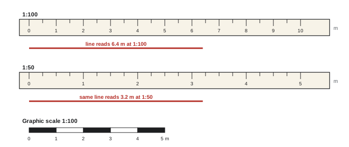
On a floor plan drawn at 1:100, a room measures 64 mm by 42 mm on a full-size print. (a) What are the room's real dimensions and area? (b) A detail of the same room's door frame is drawn at 1:5, and the frame depth measures 30 mm on the print. How deep is the frame? (c) The plan is printed at half size by mistake. What scale is it now, and what would the room measure on that print?
Show solution
- At 1:100, real length = drawing length × 100. The room is 64 × 100 = 6,400 mm = 6.4 m by 42 × 100 = 4,200 mm = 4.2 m.
- Area = 6.4 m × 4.2 m = 26.88 m², about 26.9 m².
- At 1:5, the frame depth is 30 × 5 = 150 mm.
- At half size, every drawing length halves, so the scale becomes 1:200. The room would measure 32 mm by 21 mm on that print; measuring it with the 1:100 edge would wrongly give 3.2 m by 2.1 m.
Answer: The room is 6.4 m × 4.2 m (about 26.9 m²); the frame is 150 mm deep; at half size the plan is 1:200, and using the wrong edge halves every measurement.
Half-size printing is the classic scaling error. Good drawings include a graphic scale, a bar marked in real units that is printed with the drawing and therefore shrinks or grows with it. Measuring against the graphic scale gives the right answer at any print size. When a sheet has no graphic scale and you are unsure of the print size, check a known written dimension with your scale before trusting any measurement.
Scaling from PDFs
Most drawings are now read as PDFs on screens and tablets, and PDF software includes measuring tools. These tools must be calibrated: you tell the software the scale, or better, you calibrate it against a known dimension on the drawing, such as the distance between two grid lines. Each viewport on a sheet may have a different scale, so you must recalibrate when you move from a 1:100 plan to a 1:20 section on the same sheet. Calibration against a long known dimension is more accurate than against a short one. Takeoff software used by estimators works the same way (CON-200).
Even with careful calibration, scaled measurements are approximate. Line thickness, drafting tolerances, plotting distortion and the fact that some items are drawn schematically all limit accuracy. Scaling is fine for estimating quantities and checking reasonableness. It is not acceptable for setting out the building. When the dimension you need is missing, the correct response is to calculate it from other dimensions if possible, or to ask the designer through an RFI (Lesson 11).
Dimension strings
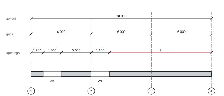
Dimensions on drawings are grouped into strings: chains of dimensions running along a line, each measured from one reference point to the next. On a typical floor plan:
- The outermost string gives the overall dimension of the building or wall.
- The next string in gives distances between grid lines or major structural elements.
- Inner strings locate openings, wall junctions and other features.
Each dimension in a string runs between two reference points, and the drawing or general notes tell you what they are: grid lines, the centre lines of columns or openings, the face of concrete or masonry, the face of stud, or the face of finish. On many architectural drawings, interior partitions are dimensioned to the face of stud or to the centre line of the partition, and openings to their centre lines or to rough openings; general notes state which.
A well-dimensioned drawing has strings that add up: the sum of the parts equals the overall dimension. When a string does not close, something is wrong, and you must find out what before building. Dimensions that are deliberately not given, so that a tolerance has somewhere to go, are sometimes marked with a note such as "±" or "VIF", or simply left as one open dimension in a string.
Worked problem
Calculating a missing dimension
An exterior wall runs from grid 1 to grid 4, with grids spaced 6 000 mm. The inner dimension string reads: 1 200 from grid 1 to the edge of window 1, window 1 width 1 800, 3 000 between windows, window 2 width 1 800, then a missing dimension to grid 4. Find the missing dimension, and check whether window 2 is centred between grids 3 and 4.
Show solution
- Overall grid 1 to grid 4: 3 × 6 000 = 18 000 mm.
- Known parts: 1 200 + 1 800 + 3 000 + 1 800 = 7 800 mm.
- Missing dimension: 18 000 − 7 800 = 10 200 mm.
- Window 2 runs from 7 800 − 1 800 = 6 000 mm to 7 800 mm from grid 1, that is, from grid 2 (at 6 000) to 1 800 beyond it. So window 2 lies between grids 2 and 3, not 3 and 4, and is not centred in any bay; its centre is at 6 900 mm, 900 mm past grid 2.
Answer: The missing dimension is 10 200 mm. Window 2 starts at grid 2, so the assumption that it sits between grids 3 and 4 is wrong; checking strings against grids catches such misreadings.
Adding and subtracting feet and inches
Metric dimensions are added like any decimal numbers. Imperial dimensions require care because 12 inches make a foot and fractions of an inch are in halves, quarters, eighths and sixteenths. A reliable method is to add feet, inches and fractions separately, then carry: 7'-8 3/4" + 5'-6 1/2" = 12' + 14" + 1 1/4" = 12' + 15 1/4" = 13'-3 1/4". Alternatively, convert everything to inches or decimal feet, do the arithmetic and convert back. Construction calculators that work directly in feet, inches and fractions are widely used in the US and in Canadian residential work.
Mixing units is a serious risk on projects that combine metric drawings with imperial products, or old imperial drawings of an existing building with new metric work. Convert carefully, state units explicitly and round sensibly: 1 in = 25.4 mm exactly, and 1 ft = 304.8 mm exactly.
Grid lines
Almost every building larger than a house has a grid: a set of reference lines, usually through the centres of columns or the faces of structural walls, running in two directions. One direction is lettered (A, B, C …, usually skipping I and O to avoid confusion with 1 and 0) and the other numbered (1, 2, 3 …). Each grid line ends in a grid bubble. The intersection of two grid lines, such as C-4, is an address that appears on every plan, every structural drawing and the MEP drawings.
Grids are the backbone of layout. Surveyors set out the grid on site first, and all other elements are dimensioned from the grid. Structural drawings locate columns, footings and beams by grid; architectural drawings dimension walls from grids; MEP drawings show equipment and risers by grid. When you discuss a problem on site, describing its location by grid ("the conflict is at D-7, about 1.5 m north of grid 7") ensures everyone looks at the same place.
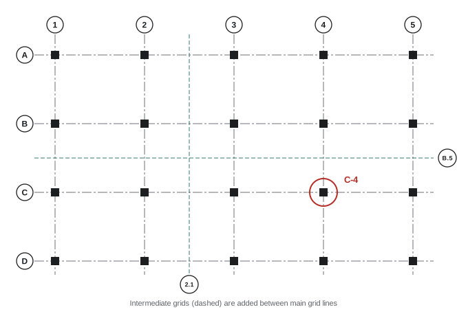
Intermediate grid lines, such as B.5 or 2.1, are added between main lines for offset elements. Curved or angled buildings use radial grids, with angles from a centre point, or separate grids for each wing. Large projects may have several grids that meet at defined angles, and the relationship between them is shown on a key plan.
Elevations and datums
Plans locate things horizontally; elevations (in the sense of heights) locate them vertically. Heights on drawings are measured from a datum, a reference level. There are two main kinds:
- A geodetic datum relates heights to mean sea level, through national survey benchmarks. Site and civil drawings normally use geodetic elevations so that grades, sewers and roads fit the surroundings.
- A project datum is a convenient local reference. Many projects set the main finished floor at 100.000 (in metres) or 100'-0" (in feet), so that all levels are positive and easy to read. Others use the actual geodetic elevation of the main floor.
Elevation values appear in spot elevations, level markers on sections and elevations (a symbol, often a circle divided into quarters with two shaded, beside a horizontal line), and notes such as "T/O SLAB EL 104.200" or "U/S DECK EL 112'-8"". A general note or the survey drawing states the relationship between the project datum and geodetic elevation, for example "Project datum 100.000 = geodetic 652.350". Lesson 5 shows how site drawings use elevations for grading and drainage.
In Canada, geodetic elevations are referenced to the Canadian Geodetic Vertical Datum of 2013 (CGVD2013), which replaced CGVD28 as the national standard; older surveys and municipal records may still use CGVD28, and the two can differ by tens of centimetres or more depending on location. Survey drawings should state which datum they use.
Tolerances
No building is built exactly to the dimensions on the drawings. Every material and trade has tolerances, acceptable deviations from the specified dimensions, set out in standards and specifications. Concrete, steel, masonry, framing and finishes have different tolerances, and when they meet, the tolerances must be compatible. Drawings and specifications sometimes state tolerances directly; otherwise they come from referenced standards (CON-110 and CON-111 cover materials tolerances). Readers should note where dimensions are critical, such as elevator shafts, prefabricated components and equipment pads, and where they leave room for adjustment.
Common mistakes
MistakeScaling a dimension for layout when it can be calculated or asked.
InsteadUse written dimensions; calculate missing ones or issue an RFI.
MistakeMeasuring a half-size print with the full-size scale.
InsteadCheck print size and use the graphic scale or a known dimension.
MistakeUsing one PDF calibration for every view on a sheet.
InsteadRecalibrate for each viewport and check against a known dimension.
MistakeAssuming dimension reference points.
InsteadCheck whether dimensions are to grid, centre line, face of stud or finish.
MistakeMixing project and geodetic elevations.
InsteadConfirm the datum relationship stated on the drawings.
Summary and key terms
- A scale relates drawing length to real length; real length = drawing length × scale factor.
- 1/4" = 1'-0" is 1:48 and 1/8" = 1'-0" is 1:96; metric plans are typically 1:100 or 1:50.
- Graphic scales stay correct when drawings are printed at other sizes.
- Written dimensions govern; scaling is for estimating and checking only.
- Dimension strings run between stated reference points and must add up.
- Grid lines give every point in plan an address used by all disciplines.
- Heights are measured from a project or geodetic datum, which drawings must state.
- Scale
- Ratio of drawing size to real size.
- Scale factor
- Multiplier from drawing length to real length.
- Graphic scale
- Scale bar that shrinks or grows with the drawing.
- Scaling
- Measuring a real length from a drawing.
- Dimension string
- Chain of dimensions along one line.
- Figured dimension
- A dimension written on the drawing.
- Grid line
- Lettered or numbered reference line for layout.
- Datum
- Reference level from which elevations are measured.
- Spot elevation
- Height of a specific point shown on a drawing.
- Tolerance
- Acceptable deviation from a specified dimension.
Practice problems
Work each problem on paper first, then reveal the answer to check.
What ratio is 1/8" = 1'-0"?
Show answer
1:96.
A line is 45 mm long on a 1:50 plan. How long is it?
Show answer
2,250 mm (2.25 m).
A line is 2 1/2" long at 1/4" = 1'-0". How long is it?
Show answer
10'-0".
A 1:100 plan is printed at half size. What scale is it?
Show answer
1:200.
Why should PDF tools be calibrated on a long known dimension?
Show answer
It reduces relative error.
Overall 12 000 mm; parts 2 400, 3 600, 2 900. Missing part?
Show answer
3,100 mm.
Add 6'-9 1/2" and 4'-5 3/4".
Show answer
11'-3 1/4".
Why are I and O often skipped in grid letters?
Show answer
To avoid confusion with 1 and 0.
What is a project datum?
Show answer
A local reference level, such as main floor = 100.000.
Which governs: a written dimension or a scaled one?
Show answer
The written dimension.
Lesson quiz · 5 questions
Score 60% or more to complete this lesson.
Create a free account to save your progress, take quizzes and earn a certificate.