
CON-120 · Lesson 5 of 12 · 27 min
Site and civil drawings
Before a building can rise, its site must be surveyed, shaped and serviced. Site and civil drawings describe that work: where the property lines are, how the ground is shaped now and how it will be shaped, where the building, roads, parking and walkways go, how rain and snowmelt will drain, and how water, sewer and other services reach the building. They are drawn by land surveyors and civil engineers, usually at small scales, and use their own conventions: contour lines, spot elevations, slopes, pipe inverts, stations and profiles. This lesson explains how to read surveys, site plans, grading plans, servicing plans, plan-and-profile sheets and erosion and sediment control plans. It focuses on reading the drawings; the earthwork and construction methods behind them belong to CON-110.
Surveys: the starting point
Two kinds of survey usually come before design. A legal or boundary survey establishes the property lines, easements, rights-of-way and encroachments. A topographic survey records the existing ground surface, buildings, trees, pavements, utilities and other features, with elevations. Together they form the base on which the civil engineer and architect design the site.
In Canada, boundary surveys are performed by provincially licensed land surveyors, such as Ontario Land Surveyors or Alberta Land Surveyors, and in federal lands and the territories by Canada Lands Surveyors. A plan of survey or a surveyor's real property report shows boundaries, buildings and encroachments, and may be registered in the provincial land registry. Topographic information is often added by the same surveyor. Before excavation, buried utilities must be located through the provincial one-call service, such as Ontario One Call or the Click Before You Dig services in other provinces.
Survey drawings show the property boundary as a heavy line with long dashes and short dashes, labelled with bearings and distances, such as "N 45°12'30" E 62.48 m". Corners are marked with symbols for found or set survey monuments. Easements, setbacks and rights-of-way are shown with their widths and purposes. Existing features are drawn with standard symbols: trees with their trunk diameters, hydrants, manholes, catch basins, light standards and utility poles.
Contour lines
The shape of the ground is shown with contour lines, lines joining points of equal elevation, like the lines on a topographic map. The vertical distance between adjacent contours is the contour interval, typically 0.25 m, 0.5 m or 1 m on metric site plans and 1 ft or 2 ft on US plans. Some contours, often every fifth one, are drawn heavier and labelled as index contours. Reading contours takes practice, but a few rules help:
- Contours never cross, except at overhangs, which are rare.
- Closely spaced contours mean steep slopes; widely spaced contours mean gentle slopes.
- Water flows downhill perpendicular to the contours.
- Contours bend upstream (in a V pointing uphill) where they cross a valley or swale, and downstream where they cross a ridge.
- Closed loops indicate a hill or a depression, depending on whether elevations rise or fall towards the centre.
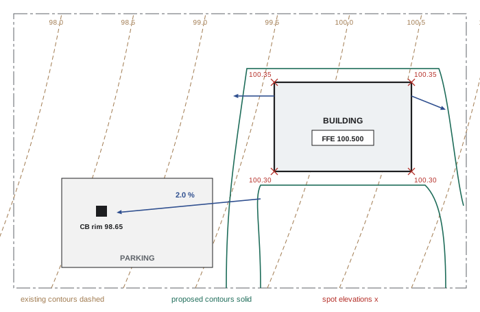
Grading plans show existing contours as thin dashed lines and proposed contours as solid lines. Where they differ, the ground will be cut or filled. Spot elevations, marked with a small cross or dot and a number, give the exact proposed elevation at key points, such as building corners, entrances, high points, low points, catch basins and the tops and bottoms of curbs and walls.
Slopes and grades
Slopes on site drawings are expressed in several ways:
- As a percentage: the rise or fall per 100 units of horizontal distance. A 2 % slope falls 2 m in 100 m, or 20 mm per metre (about 1/4 in per foot).
- As a ratio of horizontal to vertical, especially for embankments: 3:1 (or 3H:1V) means 3 units horizontally for each unit vertically.
- As a ratio of rise to run for ramps: 1:12 means one unit up for every 12 units along.
- As an angle, used less often on civil drawings.
Typical design values include at least about 1 % to 2 % for paved surfaces to drain, about 2 % cross slope on sidewalks, 5 % or more for landscaped ground falling away from a building for the first few metres, and no steeper than 3:1 for mowed grass embankments. Accessible routes and ramps have strict maximum slopes set by building codes and accessibility standards.
Worked problem
Slopes and spot elevations
A parking area drains from a spot elevation of 99.40 at the building entrance to a catch basin rim at 98.65, a horizontal distance of 37.5 m. (a) What is the slope? (b) A walkway from the entrance must not exceed a 5 % running slope; how much can it drop over 18 m? (c) An embankment at 3:1 rises 1.8 m; how wide is it in plan?
Show solution
- Change in elevation: 99.40 − 98.65 = 0.75 m.
- Slope = 0.75 ÷ 37.5 × 100 = 2.0 %.
- Maximum walkway drop: 18 m × 0.05 = 0.90 m.
- Embankment width: 3 × 1.8 m = 5.4 m horizontally.
Answer: The parking slope is 2.0 %; the walkway can drop at most 0.90 m over 18 m; the embankment is 5.4 m wide in plan.
Interpolating between contours
You often need the elevation of a point that lies between two contours. If the ground is assumed to slope uniformly between them, the elevation can be found by linear interpolation: measure the distance from the lower contour to the point and the total distance between the contours along the steepest line, and add the same proportion of the contour interval to the lower elevation. For example, a point 6 m from the 100.0 contour along a 10 m line to the 100.5 contour is at about 100.0 + 0.6 × 0.5 = 100.30. The difference between existing and proposed elevations at a point gives the depth of cut or fill there, which estimators use to calculate earthwork volumes.
The site plan
The site plan, often prepared by the architect with civil and landscape input, shows the building in relation to its site. It typically includes:
- Property lines, easements and the required setbacks from each line, with dimensions locating the building.
- The building footprint, entrances and finished floor elevation.
- Roads, driveways, parking stalls and aisles, loading areas, fire routes and curbs.
- Sidewalks, accessible routes, ramps and barrier-free parking.
- Fences, retaining walls, signs, lighting and site furniture.
- Zoning data: lot area, building area, coverage, height, parking counts and other figures required by the municipality.
- A north arrow, scale and key to adjacent streets.
Setbacks and building location are critical. Building in the wrong place by even a small amount can violate zoning, encroach on a neighbour or an easement, or fail to meet fire separation distances, and the consequences can be severe. That is why the building is set out from survey control by a qualified surveyor and checked by survey once the foundations are in.
Site servicing drawings
Servicing drawings show the underground pipes that bring water to the building and carry wastewater and stormwater away. The main systems are:
- Water: a service connection from the municipal main, with valves, a meter (often inside the building), fire hydrants and a fire service line for sprinklers, often separate from the domestic line.
- Sanitary sewer: a gravity pipe carrying wastewater from the building to the municipal sanitary sewer, with cleanouts and manholes.
- Storm sewer: catch basins, area drains and roof drain connections feeding pipes to the municipal storm sewer, a ditch or a stormwater management facility.
- Stormwater management: ponds, underground storage tanks or chambers, oil and grit separators and orifice controls that limit the rate of discharge to the municipal system.
- Other utilities: gas, electrical, telecommunications and district energy, often shown on the electrical or composite utility drawings.
Pipes are shown as lines labelled with their size, material and slope, such as "200 mm PVC SAN @ 1.0 %" or "8" PVC SAN @ 1.00 %". Manholes and catch basins are numbered and listed with their rim (top) elevations and the invert elevations of each pipe entering and leaving. The invert is the elevation of the inside bottom of the pipe, the level at which water flows.
Plan and profile drawings
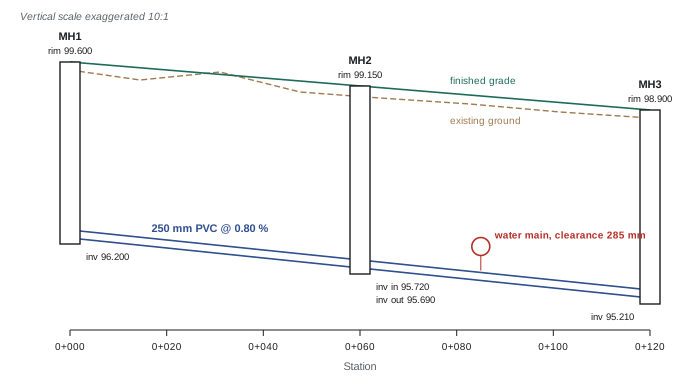
For linear work such as sewers, water mains and roads, civil drawings use plan-and-profile sheets: the plan view in the upper half of the sheet and a profile, a vertical section along the centre line, in the lower half. The profile shows the existing and proposed ground surface, the pipe with its slope and inverts, the manholes, and crossings with other utilities. Profiles use an exaggerated vertical scale, often ten times the horizontal scale, so that slopes and clearances are visible.
Positions along the centre line are given as stations. A station is the distance from a starting point, written with a plus sign.
Canadian civil drawings in metric give stations, often called chainage, in metres from the start of the alignment, written as kilometres plus metres: 0+120.000 means 120 m from the start, and 1+045.500 means 1,045.5 m.
Worked problem
Pipe inverts and slope
A 250 mm sanitary sewer leaves MH1 with an invert of 96.200 and runs 60.0 m at 0.80 % to MH2. (a) What is the invert in at MH2? (b) The outlet invert at MH2 is set 30 mm lower than the inlet. What is it? (c) The rim of MH2 is 99.150. How deep is the manhole from rim to outlet invert? (d) A water main crosses the sewer 25 m downstream of MH1, with the bottom of the water pipe at 96.550. What is the vertical clearance between the outside of the sewer (wall thickness about 15 mm) and the water main?
Show solution
- Fall over 60 m at 0.80 %: 60 × 0.008 = 0.480 m.
- Invert in at MH2: 96.200 − 0.480 = 95.720.
- Outlet invert: 95.720 − 0.030 = 95.690.
- Manhole depth: 99.150 − 95.690 = 3.460 m.
- Sewer invert at the crossing: 96.200 − 25 × 0.008 = 96.000. Top of the pipe inside is 96.000 + 0.250 = 96.250; outside is about 96.265.
- Clearance: 96.550 − 96.265 = 0.285 m, about 285 mm.
Answer: Invert in 95.720, invert out 95.690, manhole depth 3.46 m, clearance about 285 mm. Required separations between water and sewer pipes are set by provincial and municipal standards, so the engineer must confirm that this clearance is acceptable.
Erosion and sediment control plans
Construction exposes soil, and rain carries sediment off site into storm sewers, streams and wetlands. Erosion and sediment control (ESC) plans show the measures that prevent this: silt fences along the downhill edges of the site, catch basin inlet protection, stabilized construction entrances of clean stone, sediment ponds or traps, check dams in swales, slope protection with mulch or blankets, and the sequence for installing, maintaining and removing them. ESC drawings typically include inspection and maintenance notes, and the measures must be in place before stripping and grading begin.
In Canada, erosion and sediment control is regulated mainly by provinces, municipalities and conservation authorities (in Ontario), through site alteration by-laws, permits and guidelines, along with the federal Fisheries Act, which prohibits depositing harmful substances such as sediment into waters frequented by fish. Many municipalities require an ESC plan as a condition of site plan approval or a grading permit.
Paving, curbs and site details
Site drawings also show paving types, with sections giving the thickness of asphalt or concrete and of granular base and subbase layers; curb types and transitions, including depressed curbs at driveways and curb ramps at crossings; pavement markings and signs; site lighting; fences and gates; retaining walls; and landscape elements. Most of these are covered by standard details, often taken from the municipality or the provincial or state transportation department's standard drawings, which the civil sheets reference by number.
Reading site drawings together
Site work involves several disciplines on separate sheets: survey, civil grading and servicing, landscape, architectural site plan, electrical site lighting and utilities, and sometimes geotechnical recommendations. Elevations on the civil drawings must match the finished floor and entrance elevations on the architectural drawings; roof drain locations on the plumbing drawings must match storm connections on the civil drawings; and site lighting bases must avoid underground pipes. Checking these interfaces before construction prevents expensive surprises in the ground.
Common mistakes
MistakeConfusing existing and proposed contours.
InsteadCheck the legend: existing is usually dashed, proposed solid.
MistakeMixing up rim and invert elevations.
InsteadRim is the top of the structure; invert is the inside bottom of the pipe.
MistakeReading profile slopes at face value.
InsteadRemember profiles use exaggerated vertical scales.
MistakeExcavating without utility locates.
InsteadUse the one-call service and respect locate markings.
MistakeStripping the site before ESC measures are installed.
InsteadInstall silt fences and inlet protection first.
Summary and key terms
- Boundary and topographic surveys are the base for site design.
- Contours join points of equal elevation; spacing shows steepness.
- Slope (%) = elevation change ÷ horizontal distance × 100.
- Site plans locate the building by setbacks from property lines.
- Servicing drawings show pipes with sizes, slopes, rims and inverts.
- Plan-and-profile sheets use stations and exaggerated vertical scales.
- Erosion and sediment control measures must be installed before grading.
- Contour line
- Line joining points of equal elevation.
- Contour interval
- Vertical distance between adjacent contours.
- Spot elevation
- Exact elevation of a point on a grading plan.
- Setback
- Required distance from a property line to a building.
- Invert
- Elevation of the inside bottom of a pipe.
- Rim elevation
- Elevation of the top of a manhole or catch basin.
- Station
- Distance along an alignment from its starting point.
- Profile
- Vertical section along the centre line of linear work.
- Catch basin
- Structure collecting surface water into a storm sewer.
- Silt fence
- Fabric barrier trapping sediment at a site edge.
Practice problems
Work each problem on paper first, then reveal the answer to check.
What do closely spaced contours indicate?
Show answer
A steep slope.
A 40 m swale falls 0.6 m. What is its slope?
Show answer
1.5 %.
How wide is a 3:1 embankment that rises 2 m?
Show answer
6 m.
A point lies 4 m along an 8 m line from the 99.0 contour to the 99.5 contour. Elevation?
Show answer
About 99.25.
What is an invert?
Show answer
The inside bottom elevation of a pipe.
A pipe at 1.0 % runs 45 m from invert 101.20. Downstream invert?
Show answer
100.75.
What does station 0+250 mean on a metric drawing?
Show answer
250 m from the start of the alignment.
Why are profiles drawn with exaggerated vertical scales?
Show answer
To make slopes and clearances visible.
Name three erosion and sediment control measures.
Show answer
Silt fence, inlet protection, stabilized entrance, sediment trap, check dams.
Which architectural elevation must match the civil grading plan?
Show answer
Finished floor and entrance elevations.
Lesson quiz · 5 questions
Score 60% or more to complete this lesson.
Create a free account to save your progress, take quizzes and earn a certificate.