
CON-120 · Lesson 8 of 12 · 27 min
Mechanical, plumbing and fire protection drawings
Mechanical, plumbing and fire protection systems make a building habitable and safe: they heat, cool and ventilate it, bring in clean water and carry away wastewater and stormwater, and suppress fires. On many projects they account for a quarter to a third of the construction cost, and they compete for space in ceilings, shafts and walls with structure, electrical systems and each other. Their drawings rely heavily on symbols, abbreviations, single-line representations, schedules and diagrams, so they look very different from architectural drawings. This lesson explains how to read HVAC plans, equipment schedules, piping plans, plumbing plans and riser diagrams, fire protection drawings and control diagrams. CON-230 covers how these systems work and are installed; here the focus is on reading the drawings and spotting coordination issues.
The mechanical legend and general notes
Mechanical, plumbing and fire protection drawings each begin with a legend that defines dozens of symbols and abbreviations: duct fittings, diffusers and grilles, dampers, valves of many types, pumps, piping services, plumbing fixtures, drains, cleanouts and sprinkler heads. Learning the legend is the first step. Abbreviations for piping services are especially important, because many pipes look alike on plans and are distinguished only by their labels. Common examples include:
| Abbreviation | Service | Abbreviation | Service |
|---|---|---|---|
| CW or DCW | Domestic cold water | HWS / HWR | Heating water supply / return |
| HW or DHW | Domestic hot water | CHWS / CHWR | Chilled water supply / return |
| HWC or DHWR | Hot water recirculation | CD | Condensate drain |
| SAN | Sanitary drain | G | Natural gas |
| V | Vent | FP or SP | Fire protection or sprinkler pipe |
| ST or RWL | Storm drain or rainwater leader | RL | Refrigerant liquid line |
General notes on mechanical sheets cover items such as coordination responsibilities, access to equipment and valves, seismic restraint, firestopping of penetrations, testing, balancing and commissioning, and the contractor's obligation to provide offsets and fittings needed to avoid conflicts. That last point matters: MEP drawings are often diagrammatic, showing the intent and approximate routing rather than the exact path of every duct and pipe.
Diagrammatic drawings and coordination
Unlike architectural and structural drawings, many MEP plans are explicitly diagrammatic. They show what is connected to what, the sizes and approximate routes, but not every elbow, offset and hanger. A note such as "Drawings are diagrammatic and indicate general arrangement; provide all fittings and offsets required" is common. The trades then produce coordination drawings, increasingly from a combined 3-D model, that fix the exact routes of ducts, pipes, conduits and sprinkler mains in the ceiling space and resolve clashes (Lesson 11). Reading MEP drawings therefore means understanding the system intent and checking whether it can physically fit.
HVAC plans
HVAC (heating, ventilation and air conditioning) plans show the air distribution system for each floor. Ductwork is drawn in one of two ways:
- Single-line: each duct is a single line with its size noted, used on small-scale plans and schematic layouts.
- Double-line: each duct is drawn with two lines showing its actual width, used where space is tight and on coordination drawings.
Duct sizes are given as width × depth for rectangular ducts, with the first number usually the dimension seen in plan, or as a diameter for round ducts. Supply, return and exhaust ducts are distinguished by labels, line types or hatching in section. Air terminals, such as supply diffusers, return grilles and exhaust grilles, are drawn with symbols and tagged with a type and the design airflow. Variable air volume (VAV) boxes, fan coil units, dampers (balancing, motorized, fire and smoke dampers), access doors, thermostats and sensors are also shown.
Canadian mechanical drawings normally use metric units: duct sizes in millimetres (such as 600 × 400 or 300 Ø), airflow in litres per second (L/s), water flow in L/s, pressures in pascals or kilopascals and capacities in kilowatts. Some contractors and suppliers still think in imperial units, so you may meet CFM (cubic feet per minute) and inches on shop drawings and in conversation. 1 L/s ≈ 2.12 CFM.
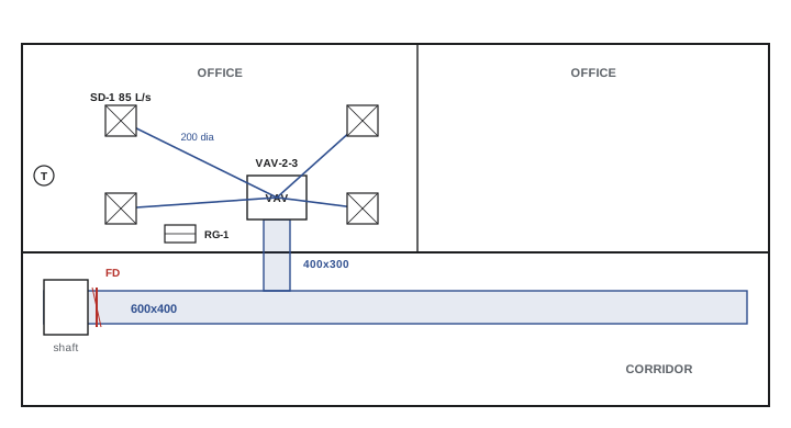
Worked problem
Airflow from diffuser tags
In the plan above, VAV-2-3 serves four SD-1 diffusers at 85 L/s each and one SD-2 diffuser at 120 L/s. (a) What design airflow must the VAV box deliver? (b) The branch duct feeding it is 400 × 300 mm. What is the air velocity in the branch? (c) The equipment schedule lists VAV-2-3 with a maximum airflow of 400 L/s. Is it adequate?
Show solution
- Total airflow: 4 × 85 + 120 = 340 + 120 = 460 L/s.
- Duct area: 0.400 × 0.300 = 0.120 m². Airflow 460 L/s = 0.460 m³/s.
- Velocity = flow ÷ area = 0.460 ÷ 0.120 ≈ 3.8 m/s, a reasonable branch velocity.
- The scheduled maximum of 400 L/s is less than the 460 L/s total of the diffusers, so the drawings disagree.
Answer: The box must deliver 460 L/s at about 3.8 m/s in the branch, but the schedule gives only 400 L/s. This is a discrepancy to raise with the mechanical engineer through an RFI before ordering the box (diffuser airflows may be diversified, or the schedule may be wrong).
Equipment schedules
Mechanical equipment is described in schedules on the drawings: air handling units (AHU), rooftop units (RTU), boilers, chillers, pumps, fans, VAV boxes, fan coils, unit heaters, heat exchangers, humidifiers and more. Each row gives the equipment tag, location, service, capacity, airflow or water flow, pressure, electrical characteristics (voltage, phase, full-load amps or kilowatts), weight, the basis-of-design manufacturer and model, and remarks. Schedules link to the electrical drawings, which must provide the right power; to the structural drawings, which must carry the weight and provide supports and openings; and to the architectural drawings, which must provide access, clearances and screens. Comparing the weight and electrical data in the mechanical schedules with the structural and electrical drawings is a routine and valuable check.
Hydronic and refrigerant piping
Heating and cooling water systems (hydronic systems) and refrigerant piping are shown on piping plans, usually single-line, with service labels, pipe sizes and flow arrows. Valves, strainers, balancing valves, expansion tanks, air separators and pumps are shown with symbols. Mechanical room plans and sections at large scale show the boiler or chiller plant, pumps and headers in detail. Piping schematics or flow diagrams show the whole system without scale, making it easier to understand how the parts connect, and they are invaluable for commissioning.
Plumbing plans
Plumbing drawings show the domestic water, sanitary drainage and vent, and storm drainage systems:
- Domestic water: cold water from the service entrance and meter, through backflow preventers, to fixtures; hot water from heaters, often with a recirculation loop; pipe sizes and valves.
- Sanitary drainage and vent: gravity drain pipes from fixtures to the building sewer, sized by fixture units and sloped, with vents that admit air and protect trap seals, and cleanouts at changes of direction and the ends of runs.
- Storm drainage: roof drains and overflow drains or scuppers, rainwater leaders down through the building, area drains and the connection to the site storm system.
- Fixtures: water closets, urinals, lavatories, sinks, showers, floor drains, drinking fountains and emergency fixtures, located on the plans and listed in a plumbing fixture schedule giving make, model, mounting height, trim and connection sizes.
Underground plumbing below the slab is usually shown on a separate plan, because it must be installed, inspected and tested before the slab is poured. Getting underground plumbing right is critical: once the slab is placed, moving a drain is expensive and disruptive.
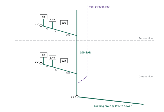
Riser diagrams, often drawn in isometric (Lesson 4), show the vertical arrangement of drains, vents and water lines through the building, with pipe sizes, fixture connections and cleanouts. They make it much easier to understand a multi-storey plumbing system than plans alone.
Worked problem
Fall of a drain pipe
A 100 mm sanitary building drain under the slab runs 18.0 m from the base of a stack to the point where it leaves the building, at a slope of 2 %. The invert at the base of the stack is 98.850. (a) What is the invert where the drain leaves the building? (b) The civil drawings show the building sewer connection invert at the foundation wall as 98.450. Do the drawings agree?
Show solution
- Fall: 18.0 m × 0.02 = 0.360 m.
- Invert at exit: 98.850 − 0.360 = 98.490.
- Civil invert at the wall: 98.450, which is 40 mm lower than the plumbing exit invert.
- A drain may enter a connection that is lower than its own invert, but a 40 mm mismatch suggests the two engineers used different assumptions; check the slope, the run length and the actual connection detail.
Answer: The drain leaves the building at 98.490, 40 mm above the civil invert. That can work, but the mismatch should be confirmed with both engineers before underground plumbing is installed.
Plumbing in Canada is governed by the National Plumbing Code of Canada as adopted by the provinces, or by provincial plumbing codes such as Part 7 of the Ontario Building Code. Minimum slopes for small drain pipes are typically 1 in 50 (2 %), with flatter slopes allowed for larger pipes.
Fire protection drawings
Fire protection drawings show sprinkler systems, standpipes, fire pumps and related equipment. On many projects, the engineer's drawings show only the design intent: the hazard classification of each area, the water supply, the location of the fire service entrance, risers, standpipes and fire department connection, and performance requirements. The sprinkler contractor's designer then lays out every head and pipe and performs hydraulic calculations, producing shop drawings that are reviewed by the engineer and, often, by the authority having jurisdiction and the owner's insurer.
Key elements on fire protection drawings include sprinkler heads (by type: pendent, upright, sidewall, concealed, dry), branch lines and cross mains with sizes, the sprinkler riser with its control valve, flow switch, tamper switch and alarm valve, the fire department connection on the exterior, standpipe hose connections in exit stairs, and the fire pump if one is needed. Hazard classifications (such as light hazard for offices and ordinary hazard for storage rooms and mechanical rooms) determine head spacing and water demand.
In Canada, the National Building Code and provincial codes require sprinklers in many buildings and reference NFPA 13 (installation of sprinkler systems), NFPA 14 (standpipes) and NFPA 20 (fire pumps), along with CAN/ULC standards for related equipment. The editions referenced depend on the code edition adopted in each province.
Controls and sequences
Building automation and controls drawings show control diagrams for each system, with sensors, actuators, controllers and points lists, and the written sequence of operations that describes how each system should operate. Controls are often designed in detail by the controls contractor, but the engineer's diagrams and sequences define what the system must do. They are essential for commissioning and are often the last part of the mechanical work to be completed.
Reading MEP drawings for coordination
A construction manager reading MEP drawings is looking for whether the systems will fit, will be supported, will be powered and will be accessible:
- Ceiling space: compare duct sizes, pipe sizes and sprinkler mains with the depth between the ceiling and the underside of the structure.
- Shafts and openings: check that shafts are big enough and that openings in slabs, walls and roofs are shown on the structural and architectural drawings.
- Rated assemblies: identify every penetration of rated walls and floors that needs fire dampers or firestopping.
- Equipment: confirm weights, curbs, housekeeping pads, clearances and access for maintenance.
- Power: confirm that every motor and piece of equipment appears on the electrical drawings with matching characteristics.
- Sequencing: identify underground and in-slab work that must be done early.
Common mistakes
MistakeTreating diagrammatic MEP routes as exact.
InsteadExpect coordination drawings to fix exact routes and offsets.
MistakeIgnoring pipe service labels.
InsteadIdentify each pipe by its abbreviation and the legend.
MistakeOrdering equipment without checking electrical and structural data.
InsteadCompare schedules across disciplines first.
MistakePouring slabs before underground plumbing is inspected and tested.
InsteadComplete, inspect and test underground work first.
MistakeAssuming the engineer's sprinkler drawings show every head.
InsteadPlan for the sprinkler contractor's design and approvals.
Summary and key terms
- MEP drawings rely on legends, symbols and service abbreviations.
- Many MEP plans are diagrammatic; coordination drawings fix exact routes.
- HVAC plans show ducts with sizes, air terminals with airflows and dampers.
- Equipment schedules link to electrical, structural and architectural requirements.
- Plumbing drawings show water, sanitary, vent and storm systems, with riser diagrams.
- Fire protection drawings often show intent, with detailed design by the sprinkler contractor.
- Reading MEP drawings means checking fit, support, power, access and sequence.
- Diagrammatic
- Showing intent and connections rather than exact routes.
- Single-line duct
- Duct drawn as one line with its size noted.
- Air terminal
- Diffuser or grille delivering or removing air.
- VAV box
- Terminal unit varying airflow to a zone.
- Equipment schedule
- Table of equipment data, capacities and electrical needs.
- Riser diagram
- Diagram of vertical piping through a building.
- Vent
- Pipe admitting air to protect trap seals.
- Cleanout
- Access fitting for clearing drain pipes.
- Hydraulic calculation
- Calculation proving a sprinkler system's water supply.
- Sequence of operations
- Written description of how a system is controlled.
Practice problems
Work each problem on paper first, then reveal the answer to check.
What does CHWS mean?
Show answer
Chilled water supply.
Why are MEP plans often diagrammatic?
Show answer
They show intent; exact routes are fixed in coordination.
Three diffusers at 90 L/s and one at 140 L/s total?
Show answer
410 L/s.
Velocity of 0.5 m³/s in a 500 × 250 mm duct?
Show answer
4.0 m/s.
Name three disciplines an equipment schedule must be checked against.
Show answer
Electrical, structural, architectural.
What is a vent in a drainage system for?
Show answer
To admit air and protect trap seals.
Fall of a 25 m drain at 1 %?
Show answer
0.25 m.
Fall of a 40 ft drain at 1/4 in per foot?
Show answer
10 in.
Who usually lays out every sprinkler head?
Show answer
The sprinkler contractor's designer.
Why is underground plumbing shown on a separate plan?
Show answer
It must be installed, inspected and tested before the slab.
Lesson quiz · 5 questions
Score 60% or more to complete this lesson.
Create a free account to save your progress, take quizzes and earn a certificate.