
CON-315 · Lesson 10 of 12 · 22 min
Field measurement, reality capture and verification
Field engineers spend as much time measuring what has been built as they do laying out what will be built. Measurement verifies that work meets tolerances, gives the next trade the information it needs to fit its components, supports progress payments and creates the as-built record. Over the past two decades, laser scanning, photogrammetry and drones have changed how much can be measured and how quickly. This lesson covers the purposes of field measurement, the main reality capture tools from a field engineer's point of view, comparing scans with the model, measuring quantities for progress, and the limits and pitfalls of the new tools. CON-250 explained how laser scanners, GNSS and drones work, and CON-260 covered reality capture as part of digital construction; here the emphasis is on using the results to make decisions on site.
Why measure the as-built condition
Every measurement should have a purpose. On Larkspur Commons, Mei measures completed work for five main reasons.
| Purpose | Examples | Who uses the result |
|---|---|---|
| Verify tolerances | Column plumbness, slab edges, floor flatness, elevator shaft | Superintendent, design team, testing agency |
| Enable the next trade | Slab edges for cladding brackets, floor heights for stairs, wall lines for prefabricated panels | Subcontractors and fabricators |
| Support payment and cost control | Quantities installed for progress claims | Project manager, subcontractors, owner |
| Detect problems early | Deflection, settlement, shrinkage, deviations from the model | Design team and site team |
| Create records | As-built positions of hidden work and finished structure | Owner, facility managers, future renovators |
Without a clear purpose, it is easy to collect large amounts of data that nobody uses. A scan of a whole floor produces hundreds of millions of points; the value lies in the few numbers extracted from it that answer a question, such as whether the slab edges are within the cladding's adjustment range.
Tools for measuring as-built conditions
Field engineers choose measurement tools based on the accuracy needed, the area to cover, access and time.
| Tool | Strengths | Limitations |
|---|---|---|
| Tape, level and string line | Simple, fast for small checks, no data processing | Limited range and accuracy over long distances; manual records |
| Total station | High accuracy on specific points; strong control link | One point at a time; needs line of sight |
| Terrestrial laser scanner | Millions of points quickly; captures whole surfaces and hidden conflicts | Large data; registration and processing needed; shadows behind objects |
| Mobile or handheld scanner | Fast coverage of large interiors by walking | Lower accuracy than static scanning; drift over long paths |
| Photogrammetry from photos or drones | Wide coverage, good for sites, stockpiles and exteriors | Accuracy depends on control and image quality; weak indoors |
| 360-degree photo capture | Visual record of every area over time, easy for anyone | Visual rather than metric; limited for tolerance checks |
Accuracy claims need care. Manufacturers quote the accuracy of individual measurements under good conditions; the accuracy of a registered point cloud depends on the scanner, the number of setups, the targets and control, the registration method and the surfaces scanned. A field engineer who uses a scan to check a tight tolerance should confirm the scan's accuracy against independently surveyed points, such as control marks or targets measured with a total station.
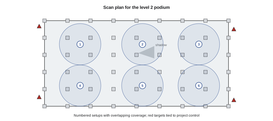
Scan-to-model comparison
A powerful use of laser scanning is comparing the as-built point cloud with the design model. Software measures the distance from each scan point to the nearest model surface and displays the result as a colour map, often called a heat map, showing where work deviates beyond tolerance. Comparisons can show walls out of position, slabs out of level, deflections, columns out of plumb and conflicts between installed services.
Comparisons are only as good as their alignment. The scan and the model must be registered to the same coordinate system using common control, not by best-fitting the scan to the model, which would hide systematic errors such as a whole wall built in the wrong place. The field engineer should insist that scans are registered to project control and checked against it.
After the level 2 core walls are stripped, the scanning technician scans the core, and Mei compares each wall face with the model.
# Scan-to-model comparison for the level 2 core walls (simulated point deviations in mm)
import random, statistics
random.seed(2027)
walls = {"Core north": (2, 4), "Core east": (-1, 3), "Core south": (6, 5), "Core west": (0, 3)}  # (mean, spread)
tol = 10   # mm, allowed deviation of the wall face from the model
for name, (mu, sd) in walls.items():
    pts = [random.gauss(mu, sd) for _ in range(5000)]       # deviation of each scan point from the model face
    within = sum(abs(p) <= tol for p in pts) / len(pts)
    out_high = sum(p > tol for p in pts) / len(pts)
    print(f"{name:10s} mean {statistics.mean(pts):+5.1f} mm  sd {statistics.stdev(pts):4.1f} mm  "
f"within {within:6.1%} beyond +{tol} mm {out_high:5.1%}")Core north mean +2.0 mm sd 4.0 mm within 97.5% beyond +10 mm 2.4% Core east mean -1.0 mm sd 3.0 mm within 99.8% beyond +10 mm 0.1% Core south mean +6.0 mm sd 5.0 mm within 79.3% beyond +10 mm 20.6% Core west mean +0.0 mm sd 3.0 mm within 99.9% beyond +10 mm 0.0%
Three walls are essentially within the 10 mm tolerance. The south wall's points average 6 mm outward with a wider spread, and about a fifth of the points are more than 10 mm beyond the design face. The pattern, outward and more variable, suggests the south wall form bowed under the concrete pressure. Mei sends the colour map to the structural engineer and the elevator installer, because the south wall forms one side of the elevator shaft. The elevator installer confirms that its rail brackets can absorb the deviation, and the formwork foreman adds walers to the south wall form before the next lift.
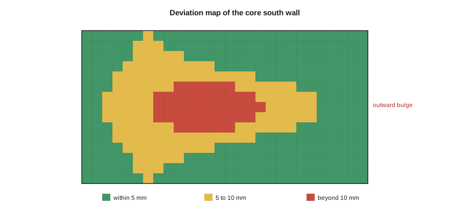
Scan comparisons are most valuable when they lead to action quickly. A colour map that arrives three weeks after the pour, when the next two levels are built, can still provide records, but it cannot prevent the problem from repeating. Many contractors scan each level within days of stripping and before key trades start, so that problems are found while they can still be fixed.
Scanning before the next trade
Lesson 8 introduced the idea of measuring before fabrication. Scanning makes it practical for large areas. On Larkspur Commons, the slab edges of the podium are scanned before the cladding subcontractor finalizes its bracket layout; the elevator shaft is scanned before rails are ordered; floor-to-floor heights are measured before the steel stairs are fabricated; and the corridor bulkheads on one wood-frame floor are scanned to confirm the space for services before the trades install their work. Each scan answers a specific question for a specific trade.
Scanning also helps before concealment. Scanning a wall or ceiling after the services are installed but before drywall closes it creates a record of what is hidden, which can save hours of exploratory demolition later. Many owners now ask for scans of concealed work as part of the record documents (lesson 11).
Drones and site-wide measurement
Drones with cameras or lidar sensors are widely used for site progress photos, earthwork volumes, stockpiles, roof inspections and exterior surveys. For a field engineer, drones are useful for measuring excavation progress against the design surface, checking stockpiles and documenting the site from above at regular intervals. Accuracy depends on ground control points tied to project control and on processing; a drone survey without control can be visually impressive and dimensionally wrong.
Drone operations are regulated. In Canada, Transport Canada's rules for remotely piloted aircraft systems require pilot certificates and registration for drones of 250 g up to 25 kg, with advanced certificates for operations near people or in controlled airspace; rules for heavier drones and beyond-visual-line-of-sight operations were updated in 2025. Kelowna's airport also brings controlled airspace close to parts of the city, so site operations may need authorization. Site safety rules and privacy considerations for neighbours apply as well.
Measuring quantities for progress
Field measurement also supports cost control. Progress payments to subcontractors are often based on the percentage of each item completed, claimed by the subcontractor and reviewed by the general contractor. CON-310 covered progress measurement and cost reporting. The field engineer's contribution is objective measurement of installed quantities, which keeps claims honest and gives the project manager a basis for discussion.
The drywall subcontractor on Larkspur Commons claims progress on level 4 by percentage complete for each item. The schedule of values sets one rate per unit area for hanging, taping and finishing, and the subcontract states that hung but untaped board earns 60 % of the rate. Arjun measures what is actually hung and fastened, from the floor plans and a walk with the 360-degree capture.
# Verify the drywall subcontractor's progress claim on level 4 from field measurement (m2, invented)
budget = {"Corridor walls": 1180, "Demising walls": 2460, "Unit interior walls": 3920, "Ceilings": 2870}
claimed = {"Corridor walls": 0.90, "Demising walls": 0.75, "Unit interior walls": 0.60, "Ceilings": 0.40}
measured = {"Corridor walls": 1050, "Demising walls": 1640, "Unit interior walls": 2380, "Ceilings": 820}  # board hung and fastened
rate = 46.0   # $ per m2 in the schedule of values (hang, tape and finish combined; hung board earns 60 %)
earn_hung = 0.60
claim_total = verified_total = 0
for item, q in budget.items():
    c = claimed[item] * q * rate
    v = measured[item] * rate * earn_hung
    claim_total += c; verified_total += v
    print(f"{item:20s} claimed {claimed[item]:4.0%}  measured hung {measured[item] / q:4.0%}  "
          f"claim ${c:9,.0f}  verified ${v:9,.0f}")
print(f"Total claimed ${claim_total:,.0f}, supported by measurement ${verified_total:,.0f}, "
f"difference ${claim_total - verified_total:,.0f}")Corridor walls claimed 90% measured hung 89% claim $ 48,852 verified $ 28,980 Demising walls claimed 75% measured hung 67% claim $ 84,870 verified $ 45,264 Unit interior walls claimed 60% measured hung 61% claim $ 108,192 verified $ 65,688 Ceilings claimed 40% measured hung 29% claim $ 52,808 verified $ 22,632 Total claimed $294,722, supported by measurement $162,564, difference $132,158
The measured hung quantities are close to the claimed percentages, so the subcontractor is not overstating how much board is up. The difference comes from the rate: the claim applies the full rate, which includes taping and finishing, to board that is only hung. Applying the 60 % earning rule cuts the supported amount from about $295,000 to about $162,000. Priya discusses the claim with the subcontractor, who resubmits it on the agreed basis. Measured quantities turn what could be an argument into a short conversation about the subcontract terms.
Monitoring movement
Some measurements track change over time rather than a single state. Field engineers may monitor settlement of adjacent buildings during excavation, movement of shoring walls, deflection of slabs after stripping, column shortening on tall buildings or wood shrinkage on mid-rise buildings like Larkspur Commons. Monitoring needs stable reference points outside the zone of movement, consistent methods and times of measurement, and trigger levels set by the engineer at which action is required.
On Larkspur Commons, the shoring engineer specified monitoring of the shoring wall along the north property line and of the neighbouring building, with review and alert trigger levels. Mei measures prisms on the shoring and on the neighbour's wall twice a week during excavation and weekly after the basement walls are poured, and sends the results to the shoring engineer. When one prism moved 12 mm, close to the review level, the engineer asked for daily readings until the movement stopped.
Managing measurement data
Reality capture produces large amounts of data, and data that cannot be found is useless. Good practice includes naming files by date, area and purpose; storing raw data, registered clouds and reports together; recording the control, instruments and registration accuracy; and linking results to the layout log and the model. Common data environments and field platforms (CON-260) help, but someone must still decide what to keep and how to name it. The field engineer often owns this responsibility for survey and scan data.
Privacy and security also apply. Scans and photos can capture people, neighbouring properties and sensitive details of a building's systems. Contractors should follow the owner's information security requirements and avoid sharing detailed scans of critical areas beyond those who need them.
Common mistakes
MistakeCollecting scans without a specific question to answer.
InsteadDefine the purpose of each measurement and extract the numbers that answer it.
MistakeBest-fitting a scan to the model before comparing.
InsteadRegister scans to project control so systematic errors are not hidden.
MistakeTrusting manufacturer accuracy figures for a registered point cloud.
InsteadCheck the cloud against independently surveyed control or targets.
MistakeScanning weeks after the work, when the next levels are built.
InsteadScan promptly after stripping and before the next trade so problems can be fixed.
MistakeAccepting progress claims without measurement.
InsteadMeasure installed quantities and apply the subcontract's earning rules.
Summary and key terms
- Field measurement verifies tolerances, enables the next trade, supports payment, detects problems and creates records.
- Choose tools based on accuracy, coverage, access and time; check point cloud accuracy against control.
- Scan-to-model comparisons show deviations as heat maps, but only if scans are registered to project control.
- Prompt scanning lets problems be corrected before they repeat on the next level.
- Measuring before the next trade or before concealment saves rework and creates valuable records.
- Drone surveys need ground control and must follow aviation rules.
- Measured quantities make progress claims objective.
- Monitoring tracks movement against engineer-set trigger levels using stable references and consistent methods.
- Reality capture
- Measuring existing conditions with scanners, cameras and drones to create digital records.
- Point cloud
- A set of measured three-dimensional points describing surfaces, produced by scanning or photogrammetry.
- Registration
- Aligning multiple scans to each other and to a coordinate system.
- Scan-to-model comparison
- Measuring the deviation of scanned surfaces from the design model.
- Heat map
- A colour-coded display of deviations from a design surface.
- Photogrammetry
- Measuring objects from overlapping photographs.
- Ground control point
- A surveyed point visible in drone images, used to tie the survey to project coordinates.
- Trigger level
- A measured movement at which a specified action, such as review or stopping work, is required.
Practice problems
Work each problem on paper first, then reveal the answer to check.
Name five purposes of field measurement.
Show answer
Verify tolerances, enable the next trade, support payment, detect problems early, create records.
Why should scans be registered to project control rather than best-fitted to the model?
Show answer
Best-fitting can hide systematic errors such as a whole wall built in the wrong place.
In the core wall example, which wall had a problem and what did the pattern suggest?
Show answer
The south wall; an outward, more variable deviation suggested the form bowed during the pour.
Why was the elevator installer told about the south wall?
Show answer
The south wall forms one side of the elevator shaft, and the rails must fit within its tolerance.
Give three examples of scanning before the next trade.
Show answer
Slab edges before cladding brackets, elevator shaft before rails, floor heights before stairs, bulkheads before services.
Why did the drywall claim differ from the measurement?
Show answer
The claim applied the full rate, including taping and finishing, to board that was only hung; hung board earns 60 %.
What makes a drone survey dimensionally reliable?
Show answer
Ground control points tied to project control and proper processing.
What three things does movement monitoring need?
Show answer
Stable references outside the zone of movement, consistent methods and times, and engineer-set trigger levels.
Lesson quiz · 5 questions
Score 60% or more to complete this lesson.
Create a free account to save your progress, take quizzes and earn a certificate.