
CON-315 · Lesson 3 of 12 · 24 min
Site control networks and gridlines
All layout on a building site depends on a small number of reference points whose positions and elevations are known and trusted. If they are wrong, everything measured from them is wrong in the same way, and the error may not show until two parts of the building fail to meet. CON-250 explained how control networks, gridlines and benchmarks are established and how control is carried up a building. This lesson looks at control from the field engineer's side: planning a control scheme that survives a real construction site, choosing coordinate systems, protecting and checking control, and using gridlines and offset lines so that every trade can work from the same reference.
Who provides control
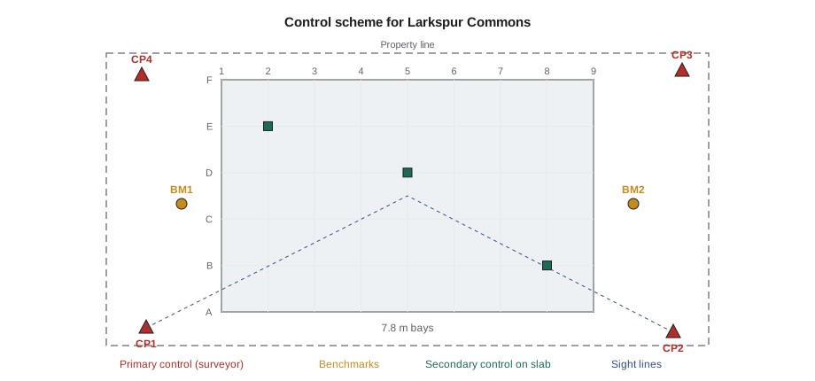
On Larkspur Commons, the owner's land surveyor, a British Columbia Land Surveyor, set the property corners and the primary control: four control points around the site and two benchmarks tied to the provincial survey network. The contract makes Thornbury responsible for everything after that: secondary control, gridlines, layout and the checks. That division is typical. Legal boundary surveys and the certificates that confirm a building's position on its lot are reserved for licensed land surveyors under provincial law, such as the Land Surveyors Act in British Columbia. Construction layout from that control is generally done by the contractor's field engineers or a layout subcontractor.
The boundary between reserved surveying and construction layout is not identical across provinces, and some activities, such as staking the building's position relative to property lines, may need a licensed surveyor's involvement. Many municipalities ask for a surveyor's certificate confirming the foundation's position before framing or later stages proceed; nearby West Kelowna, for example, publishes requirements for submitting survey certificates with building permits. The field engineer should know what the permit and the provincial rules require on each project.
Planning a control scheme
A control scheme is the arrangement of primary control, secondary control and benchmarks that will serve the project from excavation to handover. The surveyor's primary points are usually outside the building footprint, around the site perimeter. They must survive excavation, crane bases, hoarding, deliveries and site trailers for perhaps two years. The field engineer adds secondary control inside and around the building as construction progresses: offset lines on footings, control on each slab, and benchmarks on columns or walls.
Good control schemes share several features.
- Redundancy: at least three or four points visible from typical working areas, so that a disturbed point can be detected and the work continued from the others.
- Geometry: points spread around the building so that setups give strong angles and short sight lines to the work.
- Stability: points on rock, deep monuments, existing structures or well-founded concrete, away from excavation edges, haul roads and crane outriggers.
- Visibility over time: sight lines that will still exist when the podium is built, the hoarding is up and material is stacked. Points on neighbouring buildings or high on the site perimeter often last longest.
- Documentation: a control sheet with coordinates, elevations, descriptions, photos and witness ties, kept current and shared with every layout crew.
Coordinate systems: project, grid and ground
Every project uses at least two coordinate systems: the building grid, defined by gridlines and dimensions on the drawings, and a project coordinate system, used by the surveyor, the civil drawings and the model. Mixing them up causes errors that can be large.
The project coordinate system on Larkspur Commons is based on the provincial and national mapping system, here Universal Transverse Mercator coordinates on the NAD83 (CSRS) datum, with elevations on the vertical datum the surveyor specifies. Canada adopted CGVD2013 as its national vertical datum, but many municipal benchmarks and older drawings still use CGVD28, and the two can differ by tens of centimetres in places. The field engineer must confirm which datum the drawings use before using any benchmark.
Map projections introduce a scale factor: distances on the projection grid differ slightly from distances on the ground, and the difference depends on location and elevation. Surveyors usually provide ground-scaled project coordinates for building sites so that distances computed from coordinates match distances measured with a tape. The field engineer must know which kind of coordinates are in use, because the difference across one building can exceed the layout tolerance.
The building grid is usually rotated relative to the project coordinate system, because buildings follow the street, not north. To set out gridline intersections from project control, the field engineer transforms grid positions into project coordinates by a rotation and a shift, then computes the angle to turn and the distance to measure from a control point. Total stations and layout software do this automatically, but understanding the arithmetic lets the field engineer check the software and spot a wrong rotation or origin, which is a classic source of large errors.
# From the site grid to project coordinates, then layout data from a control point (m)
import math
# Grid intersection A/1 in project coordinates (UTM zone 11 based, ground-scaled, illustrative)
E0, N0 = 320_415.260, 5_526_108.740
rot = math.radians(23.500)        # the site grid y axis (grid line A toward F) points 23.5 degrees east of grid north
def to_project(x, y):
    """x along gridlines 1..9 direction (east-ish), y along A..F direction (north-ish), in m."""
    e = E0 + x * math.cos(rot) + y * math.sin(rot)
    n = N0 - x * math.sin(rot) + y * math.cos(rot)
    return e, n
bay = 7.800
pts = {"A/1": (0, 0), "A/9": (8 * bay, 0), "F/1": (0, 5 * bay), "D/5": (4 * bay, 3 * bay)}
cp1 = (320_398.112, 5_526_090.455)   # control point CP1 set by the surveyor
cp2 = (320_502.947, 5_526_142.630)   # backsight CP2
def azimuth(a, b):
    return math.degrees(math.atan2(b[0] - a[0], b[1] - a[1])) % 360
def dms(d):
    deg = int(d); m = int((d - deg) * 60); s = (d - deg - m / 60) * 3600
    return f"{deg:3d}d {m:02d}' {s:04.1f}\""
bs = azimuth(cp1, cp2)
print(f"Backsight CP1 to CP2 azimuth {dms(bs)}")
for name, (x, y) in pts.items():
    p = to_project(x, y)
    az = azimuth(cp1, p); dist = math.dist(cp1, p)
    turn = (az - bs) % 360
    print(f"{name:4s} E {p[0]:.3f} N {p[1]:.3f}  turn {dms(turn)}  distance {dist:7.3f} m")
# Grid (map projection) distance versus ground distance across the building
csf = 0.99962                     # combined scale factor near the site (illustrative)
ground = 8 * bay
print(f"A/1 to A/9: ground {ground:.3f} m, unscaled grid {ground * csf:.3f} m, difference {(ground - ground*csf)*1000:.0f} mm")Backsight CP1 to CP2 azimuth 63d 32' 27.9" A/1 E 320415.260 N 5526108.740 turn 339d 37' 15.6" distance 25.068 m A/9 E 320472.485 N 5526083.858 turn 31d 31' 40.3" distance 74.665 m F/1 E 320430.811 N 5526144.505 turn 327d 37' 54.8" distance 63.172 m D/5 E 320453.203 N 5526117.758 turn 0d 05' 44.9" distance 61.486 m A/1 to A/9: ground 62.400 m, unscaled grid 62.376 m, difference 24 mm
The output gives the coordinates of each gridline intersection and the turned angle and distance from CP1 with CP2 as the backsight. The last line shows why the coordinate type matters: across the 62.4 m building, unscaled projection coordinates would be 24 mm shorter than the ground distance, several times a typical layout tolerance for anchor bolts. With ground-scaled coordinates, as the surveyor provided here, the computed and taped distances agree.
The rotation in the example is 23.5 degrees. If a field engineer entered 23.05 degrees by mistake, a point 75 metres from the instrument would be set about 0.6 metres out of position. An independent check from a second control point or a taped check between gridlines would catch it immediately, which is why lesson 1 insisted on independent checks.
Gridlines and offset lines
Gridlines are the language of the building. Every trade locates its work by grid: column D/5, the wall 600 mm off grid 3, the sleeve 450 mm north of grid 4. Once concrete is placed or forms are erected, the gridlines themselves are buried or blocked, so field engineers set offset lines, usually a round distance away, that remain visible and usable. On Larkspur Commons, Mei sets offset lines one metre from each gridline on every slab, marked with chalk, paint and the gridline label and offset distance at regular intervals.
Choosing offsets is a practical decision. One metre is common in metric work because it is easy to measure from and clears most columns and walls. The offset should be consistent across the project and marked so clearly that nobody mistakes an offset line for the gridline itself, for example '1 m OFFSET GRID 4' written along the line with an arrow toward the gridline.
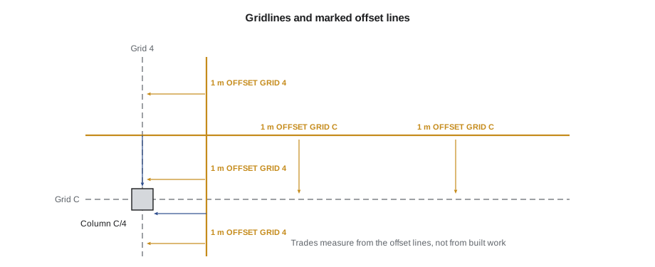
Trades should be encouraged to measure from the nearest offset line rather than from the edge of a slab, a column face or each other's work. Measuring from built work brings that work's errors into the new work and is a common cause of walls that drift or doors that do not line up. When a foreman asks where to measure from, the answer should always be the control or the offset lines.
Elevation control and benchmarks
Elevations follow the same principle. The surveyor's two benchmarks are tied to the vertical datum. Mei sets working benchmarks inside the building, such as marks on columns at exactly 1.000 m above the finished floor elevation of each level, known as the one-metre line, so that trades can measure heights with a tape or laser without carrying levels from outside. Each working benchmark is checked by a closed level loop from the primary benchmarks, as CON-250 described.
Drawings often show elevations both as project elevations and as relative values, such as 'top of slab 0.000' for the ground floor. The relationship between the two must be stated clearly on the control sheet. Confusion between architectural and structural elevations is another classic source of error: structural drawings typically show top of structural slab, architectural drawings show finished floor, and the difference is the thickness of the topping, the flooring or the drainage slope.
Protecting and checking control
Construction sites destroy control. Excavators, loaders, crane outriggers, material stacks and well-meaning labourers all move or bury points. A disturbed point that looks undisturbed is worse than a missing one, because people keep using it. The field engineer's defence is to protect points physically, with guards, paint, flagging and signs, and to check control regularly and whenever something seems wrong.
On Larkspur Commons, Mei starts each week by checking the control from a station on a known point, measuring to all the other points and benchmarks and comparing the results with their recorded values.
# Monday control check: measured positions of site control against their recorded values (mm)
import math
# measured minus recorded (dE, dN, dH) in mm, from a resection with CP1 as the station
measured = {"CP1": (0, 0, 0), "CP2": (2, -1, 1), "CP3": (-3, 2, -2),
            "CP4": (11, -14, -6), "BM1": (None, None, 1), "BM2": (None, None, -2)}
tol_h, tol_v = 5, 3     # mm allowed before a point is treated as disturbed
for p, (de, dn, dh) in measured.items():
    if de is None:
        ok = abs(dh) <= tol_v
        print(f"{p}: height {dh:+d} mm  {'OK' if ok else 'DISTURBED - do not use'}")
    else:
        d = math.hypot(de, dn)
        ok = d <= tol_h and abs(dh) <= tol_v
print(f"{p}: horizontal {d:4.1f} mm, height {dh:+d} mm {'OK' if ok else 'DISTURBED - do not use'}")CP1: horizontal 0.0 mm, height +0 mm OK CP2: horizontal 2.2 mm, height +1 mm OK CP3: horizontal 3.6 mm, height -2 mm OK CP4: horizontal 17.8 mm, height -6 mm DISTURBED - do not use BM1: height +1 mm OK BM2: height -2 mm OK
Three control points and both benchmarks agree with their recorded values within a few millimetres. CP4 has moved about 18 mm horizontally and 6 mm down, consistent with the material stacked beside it last week. Mei marks CP4 as disturbed on the control sheet and in the field, tells the layout crew and the subcontractors who use it, and asks the surveyor to re-establish it. Until then, all work uses the other points.
Tolerances for control checks depend on the instruments and the work, and are usually much tighter than the tolerances for the work itself, because control errors pass into everything. The project specification or the surveyor may set them; otherwise the field engineer should set them in the control plan.
Carrying control up the building
As the building rises, control is transferred to each new slab. CON-250 described the methods: plumbing up through small openings left in each slab using an optical or laser plummet, or resecting a total station on the slab from perimeter control. For the field engineer, the important points are planning and checking. Openings for plumbing must be shown on the deck layout and protected from being filled with concrete. Points transferred up should be checked against each other: distances and angles between transferred points should match the design, and differences show transfer errors or movement.
Concrete structures shorten slightly under load and over time, and tall buildings sway and move with temperature. On a six-storey building like Larkspur Commons, these effects are small and the main concern is consistency between floors. On high-rise projects, engineers predict column shortening and adjust floor elevations as they build, and surveyors take readings at consistent times of day to avoid thermal movement. Wood-frame floors shrink as the lumber dries, which lesson 5 discusses.
The control sheet and layout log
Every control point and every significant layout operation should be recorded. The control sheet lists each point with its coordinates, elevation, description, photo, date established, who established it, check history and status. The layout log, introduced in lesson 1, records what was laid out, from which control, using which drawing revision, by whom and how it was checked. Together they let anyone answer the question every dispute eventually asks: how do we know this was in the right place?
| Record | Contents | Updated |
|---|---|---|
| Control sheet | Point ID, coordinates, elevation, datum, description, photo, witness ties, status, check history | When points are set, checked or disturbed |
| Layout log | Date, area, items set, control used, drawing revision, instrument, crew, checker, results | Every layout session |
| Field book or digital job file | Raw observations, setups, backsights, residuals | Automatically or each session |
| Benchmark list | Working benchmarks per level, elevation, check loop and closure | When benchmarks are set or checked |
Common mistakes
MistakeUsing a control point because it looks undisturbed.
InsteadCheck control regularly and before critical layout; treat any point that fails a check as disturbed until re-established.
MistakeMixing projection grid coordinates and ground distances.
InsteadConfirm with the surveyor which coordinate type is in use and check computed distances against taped ones.
MistakeLetting trades measure from slab edges, column faces or each other's work.
InsteadMeasure from control and offset lines so that errors in built work are not passed on.
MistakeMarking offset lines without labels.
InsteadLabel each offset line with its gridline, offset distance and direction so it cannot be mistaken for the gridline.
MistakeAssuming all benchmarks are on the same vertical datum.
InsteadConfirm the datum on the drawings and the control sheet before using any benchmark.
Summary and key terms
- Licensed land surveyors set boundaries and primary control; the contractor usually provides secondary control and layout.
- A good control scheme is redundant, well spread, stable, visible over time and documented.
- Projects use both a building grid and a project coordinate system; layout requires a rotation and shift between them.
- Map projections introduce scale factors, so the field engineer must know whether coordinates are ground-scaled.
- Offset lines keep gridlines usable after forming and must be clearly labelled.
- Working benchmarks on each level let trades measure heights, and must be checked by closed level loops.
- Control must be protected and checked regularly; disturbed points are marked and not used.
- Control sheets and layout logs record how every important point was established and checked.
- Primary control
- Control points established by the surveyor, usually around the site perimeter, from which all other control is derived.
- Secondary control
- Control points added by the contractor inside and around the building as work progresses.
- Benchmark
- A stable point of known elevation used as a reference for heights.
- Offset line
- A line marked at a set distance from a gridline so that the grid remains usable after forming.
- Scale factor
- The ratio between distances on a map projection grid and distances on the ground.
- Ground-scaled coordinates
- Project coordinates adjusted so that distances computed from them match ground measurements.
- Vertical datum
- The reference surface to which elevations are referred.
- Control sheet
- A record of each control point with its coordinates, elevation, description, status and checks.
Practice problems
Work each problem on paper first, then reveal the answer to check.
Why should primary control usually be outside the building footprint?
Show answer
So that it survives excavation and construction and remains visible for the whole project.
Name four features of a good control scheme.
Show answer
Redundancy, good geometry, stability, visibility over time, documentation.
In the example, how much shorter would unscaled projection distances be across the building?
Show answer
About 24 mm across 62.4 m.
Why is a wrong rotation between the grid and project coordinates dangerous?
Show answer
It shifts points by an amount that grows with distance from the instrument, so far points can be badly misplaced while near ones look fine.
What should happen when a control check shows a point has moved?
Show answer
Mark it as disturbed, tell everyone who uses it, use other points and have it re-established.
Why must offset lines be labelled?
Show answer
So nobody mistakes an offset line for the gridline or measures in the wrong direction.
Why might architectural and structural elevations differ?
Show answer
Structural drawings show top of structural slab; architectural drawings show finished floor, which includes topping or flooring.
What two records together show how a point was established and checked?
Show answer
The control sheet and the layout log.
Lesson quiz · 5 questions
Score 60% or more to complete this lesson.
Create a free account to save your progress, take quizzes and earn a certificate.