
MEC-210 · Lesson 10 of 12 · 27 min
Planar kinetics of rigid bodies: force and acceleration
With rigid-body kinematics in hand, we can now ask the kinetic questions that matter most in machine design. How much torque does a motor need to bring a conveyor drum up to speed in three seconds? Will a tall load tip over when a shuttle brakes, or slide first? What force does a bearing feel when a crank spins? Will a roll of film roll down a ramp or skid? Each needs two equations working together: the second law for the motion of the centre of mass, and a moment equation for the rotation. This lesson develops both, introduces the mass moment of inertia that governs rotation, and applies them to the three kinds of planar motion.
Mass moment of inertia
A body's mass measures how hard it is to accelerate in a straight line. Its mass moment of inertia measures how hard it is to spin up about an axis. For a body made of mass elements \(dm\) at distances \(r\) from the axis,
Mass far from the axis counts much more than mass near it, because of the square. A flywheel is built with a heavy rim and a light hub for exactly this reason: it stores as much rotational inertia as possible per kilogram. The units are kilogram-square metres in SI and slug-square feet in US customary units.
The radius of gyration \(k\) is defined by \(I = m k^2\): it is the distance from the axis at which all the mass could be concentrated to give the same moment of inertia. Manufacturers of motors, gearboxes and pulleys often list inertia directly, but older catalogues and some industries quote the related quantity \(W k^2\), or \(GD^2\), so check the definition before using a number.
| Body (uniform) | Axis | I |
|---|---|---|
| Slender rod, length L | Through centre, perpendicular to rod | mL²/12 |
| Slender rod, length L | Through one end, perpendicular to rod | mL²/3 |
| Solid cylinder or disc, radius r | Central axis | mr²/2 |
| Thin ring or hoop, radius r | Central axis | mr² |
| Thick-walled tube, radii r₁ and r₂ | Central axis | m(r₁² + r₂²)/2 |
| Solid sphere, radius r | Any diameter | 2mr²/5 |
| Rectangular plate, sides a and b | Through centre, perpendicular to plate | m(a² + b²)/12 |
The parallel-axis theorem gives the moment of inertia about any axis parallel to one through the centre of mass \(G\), a distance \(d\) away:
The rod results in the table illustrate it: \(mL^2/12 + m(L/2)^2 = mL^2/3\). For composite bodies, such as a drum made of a shell, two end discs and a shaft, add the moments of inertia of the parts about the same axis, using the parallel-axis theorem for any part whose centre of mass is not on the axis, and subtracting holes.
Equations of motion for a rigid body in plane motion
A rigid body is a system of particles, so Lesson 7 already gives the first equation: the resultant external force equals the total mass times the acceleration of the centre of mass. Summing moments of the particle equations about \(G\), and using the fact that the particles keep fixed distances, gives the second:
Three scalar equations for a body in plane motion. The moment equation must be written about the centre of mass \(G\), or about a fixed axis of rotation, unless the kinetic moment of \(m\mathbf{a}_G\) is included. In general, for moments about any point \(P\),
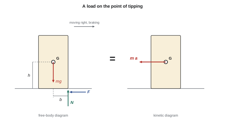
This form is often the most efficient, because choosing \(P\) at the intersection of two unknown forces removes them from the equation. It is easiest to apply by drawing the kinetic diagram: the body with a vector \(m\mathbf{a}_G\) at \(G\) and a couple \(I_G\alpha\). The moments of the external forces on the free-body diagram about any point equal the moments of \(m\mathbf{a}_G\) and \(I_G\alpha\) about the same point on the kinetic diagram.
Translation
When a body translates, \(\alpha = 0\), so \(\sum M_G = 0\): the forces have no net moment about the centre of mass, even though the body accelerates. This is enough to decide when a load on an accelerating vehicle tips over. The friction force at the base acts at floor level, below the centre of mass, and its moment tends to tip the load forward when the vehicle brakes. The load stays upright only if the normal force can shift far enough forward to balance that moment. When the normal force reaches the front edge of the base, the load is on the point of tipping.
Worked problem
Will the tall tote tip or slide?
A loaded tote stands on a shuttle deck. Its centre of mass is 0.35 m above the deck and 0.15 m behind the front edge of its base (in the direction of travel). The coefficient of static friction between tote and deck is 0.60. As the shuttle brakes, does the tote slide first or tip first, and at what deceleration?
Show solution
- The tote decelerates with the shuttle, so \(m\mathbf{a}_G\) points backward with magnitude \(ma\). Friction \(F\) acts backward at the base; the normal force \(N = mg\) acts at some point under the base.
- Sliding: \(F = ma \le \mu_s mg\), so sliding starts at \(a = \mu_s g = 0.60(9.81) = 5.89 \text{ m/s}^2\).
- Tipping: at the point of tipping, \(N\) acts at the front edge \(E\). Take moments about \(E\): the weight's moment \(mg\,b\) must balance the moment of \(m a\) at height \(h\):
- \[mg(0.15) = ma(0.35) \;\Rightarrow\; a = g\frac{b}{h} = 9.81\frac{0.15}{0.35} = 4.20 \text{ m/s}^2\]
- Tipping needs less deceleration than sliding, so the tote tips first, at 4.20 m/s².
Answer: The tall tote tips at 4.20 m/s², about 0.43 g, before it would slide. A low tote, with its centre of mass at 0.20 m, would instead slide at 5.89 m/s² and need 7.36 m/s² to tip.
The comparison turns into a simple rule: tipping governs whenever \(h > b/\mu_s\), that is, when the load is tall compared with its base and the friction is good. Good friction is not always good news: a grippy deck mat that stops totes sliding can make tall ones tip instead. The program below tabulates both limits for a range of load heights and works out an allowable braking rate for a shuttle that must handle every load up to 0.45 m tall, with a safety factor of 1.5.
# A load stands on a shuttle deck that brakes at deceleration a.
# It slides if a > mu_s g, and tips forward if a > g b / h, where b is
# the distance from the centre of mass to the front edge of the base
# (measured horizontally) and h is the height of the centre of mass.
g, mu_s, b = 9.81, 0.6, 0.15        # m/s^2, -, m

print("  h (m)   slide at (m/s^2)   tip at (m/s^2)   what happens first")
for h in (0.10, 0.15, 0.20, 0.30, 0.35, 0.45):
    a_slide = mu_s * g
    a_tip = g * b / h
    first = "slides" if a_slide < a_tip else "tips"
    print(f"  {h:4.2f}   {a_slide:10.2f}        {a_tip:10.2f}        {first}")

h_crit = b / mu_s
print(f"tipping governs when h > b / mu_s = {h_crit:.3f} m")

# Braking limit for a shuttle that must not upset any load up to h = 0.45 m,
# with a safety factor of 1.5 on both sliding and tipping:
a_allow = min(mu_s * g, g * b / 0.45) / 1.5
print(f"allowable braking deceleration: {a_allow:.2f} m/s^2 ({a_allow / g:.2f} g)")h (m) slide at (m/s^2) tip at (m/s^2) what happens first 0.10 5.89 14.71 slides 0.15 5.89 9.81 slides 0.20 5.89 7.36 slides 0.30 5.89 4.91 tips 0.35 5.89 4.20 tips 0.45 5.89 3.27 tips tipping governs when h > b / mu_s = 0.250 m allowable braking deceleration: 2.18 m/s^2 (0.22 g)
An allowable deceleration of about 0.22 g is far below what the shuttle's brakes can deliver. That is typical. The limit on how fast an automated vehicle can stop is often set by its load, not its brakes, and controllers are programmed with separate deceleration limits for normal stops and emergency stops, with the emergency case checked against the worst load the system is allowed to carry.
Rotation about a fixed axis
For a body rotating about a fixed axis through \(O\), the centre of mass moves on a circle, so \((a_G)_t = \alpha r_G\) and \((a_G)_n = \omega^2 r_G\). The moment equation is most conveniently written about the axis itself, where the bearing reactions have no moment:
The force equations then give the bearing reactions. If the centre of mass lies on the axis, as it should for any well-balanced rotor, \(\mathbf{a}_G = 0\) and the bearings carry only the static loads. If it does not, the bearings must supply the force \(m\omega^2 r_G\) to keep the centre of mass on its circle, a force that rotates with the shaft and grows with the square of speed. A rotor with its centre of mass just 0.1 mm off the axis, spinning at 3,000 rev/min, needs a rotating force of about 10 N per kilogram of rotor mass: that is the source of most machine vibration, and the reason rotors are balanced.
Worked problem
Starting torque for a conveyor drive
A conveyor drive drum of radius 0.20 m has a moment of inertia of 1.8 kg·m² about its axis, including the gearbox output referred to the drum. The belt and its load have a combined mass of 300 kg, and steady running resistance (rolling of idlers, belt flexing) amounts to 400 N at the belt. Find the torque the drive must apply to the drum to accelerate the belt at 1.0 m/s².
Show solution
- Angular acceleration of the drum: \(\alpha = a/r = 1.0/0.20 = 5.0 \text{ rad/s}^2\).
- The belt pulls back on the drum with a net force equal to what it needs to accelerate itself and its load, plus the resistance: \(F = 300(1.0) + 400 = 700 \text{ N}\).
- \[\sum M_O = T - F r = I_O\,\alpha \;\Rightarrow\; T = 700(0.20) + 1.8(5.0) = 140 + 9 = 149 \text{ N·m}\]
Answer: The drive must supply 149 N·m during acceleration, compared with 80 N·m for steady running. The drum's own inertia adds only 9 N·m, but the motor's rotor, seen through the gearbox ratio, can add much more, as the next paragraph explains.
Inertia seen through a gear reduction is multiplied by the square of the ratio. A motor rotor with an inertia of only 0.005 kg·m², driving through a 20 to 1 gearbox, looks like \(0.005 \times 20^2 = 2.0 \text{ kg·m}^2\) at the drum, more than the drum itself. Designers of servo systems keep track of this reflected inertia carefully, because a motor whose own inertia dominates the load spends most of its torque accelerating itself.
General plane motion
For general plane motion all three equations are needed, usually together with a kinematic relation between \(a_G\) and \(\alpha\). The commonest case is a wheel, roller or cylinder that may roll, slip or do some of each. The method is to assume rolling without slipping, which gives \(a_G = \alpha r\), solve, and then check whether the friction force required is less than \(\mu_s N\). If it is not, the body slips: replace the rolling relation with \(F = \mu_k N\) and solve again.
Worked problem
A roll of film on a ramp
A 15 kg roll of stretch film, which can be treated as a solid cylinder, is released on a ramp inclined at 10°. Find its acceleration if it rolls without slipping, and the smallest coefficient of static friction that allows it to roll.
Show solution
- Forces: weight \(mg\), normal force \(N = mg\cos 10^\circ\), friction \(F\) up the slope at the contact point.
- Along the slope: \(mg\sin 10^\circ - F = m a_G\). Moments about \(G\): \(F r = I_G\alpha = \tfrac12 m r^2 \alpha\). Rolling: \(a_G = \alpha r\).
- From the moment equation, \(F = \tfrac12 m a_G\). Substituting: \(mg\sin 10^\circ = \tfrac32 m a_G\), so \(a_G = \tfrac23 g\sin 10^\circ = \tfrac23(9.81)(0.1736) = 1.14 \text{ m/s}^2\).
- Friction needed: \(F = \tfrac12(15)(1.14) = 8.52 \text{ N}\). Available: \(\mu_s N = \mu_s(15)(9.81)(0.985)\).
- Rolling requires \(\mu_s \ge F/N = \tfrac13\tan 10^\circ = 0.059\).
Answer: The roll accelerates at 1.14 m/s², two-thirds of what a frictionless sliding block would do, and it needs a friction coefficient of only 0.059 to roll. Almost any real ramp will make it roll.
The factor of two-thirds is the fraction of the potential energy that goes into translation; the rest goes into spinning. A hoop, with all its mass at the rim, would accelerate at only half the sliding-block value; a solid sphere at five-sevenths. Lesson 11 explains these results with energy, which is often the faster route.
Common mistakes
MistakeWriting ΣM = Iα about an arbitrary point.
InsteadUse the centre of mass or a fixed axis, or include the moment of m a_G.
MistakeAssuming a translating body has no moments acting on it.
InsteadThe net moment about G is zero, but forces still have moments about other points.
MistakeAssuming the friction force on a rolling body equals μN.
InsteadFind the friction needed for rolling, then check it against μ_s N.
MistakeForgetting reflected inertia of motors and gearboxes.
InsteadMultiply rotor inertia by the square of the gear ratio.
MistakeUsing I_G when the body rotates about a fixed axis away from G.
InsteadUse I_O = I_G + m d² for moments about the fixed axis.
Summary and key terms
- I = ∫r² dm; mass far from the axis dominates.
- Parallel-axis theorem: I = I_G + md².
- ΣF = m a_G and ΣM_G = I_G α; or ΣM_P = I_G α + moment of m a_G about P.
- For translation, ΣM_G = 0; a load tips when a > gb/h and slides when a > μ_s g.
- For fixed-axis rotation, ΣM_O = I_O α; an off-axis centre of mass loads the bearings with mω²r_G.
- Reflected inertia through a gear ratio n is n² times the motor inertia.
- For rolling, assume no slip, then check the friction needed against μ_s N.
- Mass moment of inertia
- The resistance of a body to angular acceleration about an axis, ∫r² dm.
- Radius of gyration
- The distance k such that I = mk².
- Parallel-axis theorem
- I = I_G + md² for parallel axes a distance d apart.
- Kinetic diagram
- A sketch showing m a_G at G and the couple I_G α.
- Tipping
- Rotation of a load about an edge of its base.
- Reflected inertia
- The inertia of a component as felt at another shaft through a gear ratio.
- Balancing
- Adjusting mass so a rotor's centre of mass lies on its axis.
- Rolling without slipping
- Rolling with a_G = αr and static friction at the contact.
Practice problems
Work each problem on paper first, then reveal the answer to check.
Find I for a 20 kg solid disc of radius 0.25 m about its axis.
Show answer
I = ½ x 20 x 0.25² = 0.625 kg·m².
A 2 kg slender rod 0.6 m long pivots at one end. What is I about the pivot?
Show answer
I = 2 x 0.6²/3 = 0.24 kg·m².
In the tote example, how tall can the centre of mass be before tipping governs?
Show answer
h = b/μ_s = 0.15/0.60 = 0.25 m.
What drum torque would the conveyor need at 2.0 m/s² acceleration?
Show answer
F = 600 + 400 = 1000 N; T = 200 + 1.8 x 10 = 218 N·m.
A hoop rolls down the 10° ramp. What is its acceleration?
Show answer
a = ½ g sin 10° = 0.852 m/s².
In the program, what allowable deceleration results if the deck friction rises to 0.8?
Show answer
Still 2.18 m/s², because tipping of the 0.45 m load governs.
Lesson quiz · 5 questions
Score 60% or more to complete this lesson.
Create a free account to save your progress, take quizzes and earn a certificate.