
MEC-210 · Lesson 8 of 12 · 24 min
Planar kinematics of rigid bodies
A particle has a position but no orientation. Most machine parts have both. A conveyor drum turns, a crank swings, a connecting rod both moves and rotates, and a robot link carries its gripper round an arc while tilting it. To describe such motion we need the rigid-body model: a body in which the distance between any two points never changes. Real parts deform slightly under load, but for kinematics and most kinetics the deformation is far too small to matter. This lesson and the next cover rigid bodies moving in a plane, which covers the great majority of mechanisms: cranks, linkages, cams, gears, wheels and most robot joints. Three-dimensional rigid-body motion, as in gyroscopes and spinning tops, belongs to a later course.
Types of planar motion
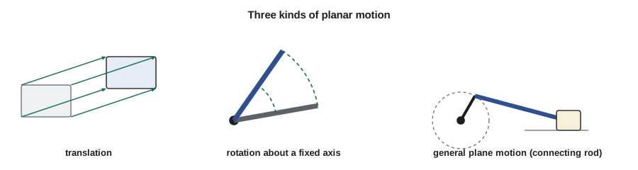
Every planar motion of a rigid body is one of three types, or a combination of them.
- Translation: every line in the body stays parallel to its original direction. In rectilinear translation all points move along parallel straight lines, like a drawer or a lift carriage. In curvilinear translation they move along congruent curves, like the platform of a parallel-link lift or the seat of a Ferris wheel. Either way, every point has the same velocity and acceleration, so the body can be treated as a particle.
- Rotation about a fixed axis: every point moves on a circle centred on the axis, like a drum, a flywheel or a fan.
- General plane motion: a combination of translation and rotation, like a connecting rod, a rolling wheel or a ladder sliding down a wall.
Angular motion
The orientation of a rigid body in the plane is described by the angle \(\theta\) that any line in it makes with a fixed reference direction. Because the body is rigid, every line in it turns through the same angle in the same time, so the body has a single angular position, angular velocity and angular acceleration:
These are exact analogues of the rectilinear relations in Lesson 1, with \(\theta\), \(\omega\) and \(\alpha\) in place of \(s\), \(v\) and \(a\). For constant angular acceleration \(\alpha_c\):
Angles must be in radians for these and all the formulas that follow. Machine speeds are usually quoted in revolutions per minute: multiply by \(2\pi/60\), or roughly divide by 9.55, to get radians per second. In plane motion, angular velocity and acceleration are vectors perpendicular to the plane; we usually take counterclockwise as positive and write them as \(\omega\mathbf{k}\) and \(\alpha\mathbf{k}\).
Points on a body rotating about a fixed axis
A point at distance \(r\) from the axis moves on a circle of radius \(r\). Its speed and the components of its acceleration follow directly from the normal-tangential results of Lesson 2:
The velocity is tangent to the circle, the tangential acceleration is along the tangent, and the normal acceleration points toward the axis. In vector form, with \(\mathbf{r}\) drawn from any point on the axis to the point in question,
These vector forms do the bookkeeping of directions automatically, which becomes valuable for linkages.
Worked problem
Spinning up a conveyor drive drum
The drive drum of a belt conveyor has a radius of 0.20 m. At start-up it accelerates uniformly from rest to 150 rev/min in 3.0 s. Find its angular acceleration, the number of revolutions it makes while speeding up, the final belt speed (if the belt does not slip), and the acceleration of a point on the drum surface 1.0 s after start-up.
Show solution
- Final speed: \(\omega = 150(2\pi/60) = 15.71 \text{ rad/s}\). Angular acceleration: \(\alpha = 15.71/3.0 = 5.236 \text{ rad/s}^2\).
- Angle turned: \(\theta = \tfrac12 \alpha t^2 = \tfrac12(5.236)(3.0)^2 = 23.6 \text{ rad} = 3.75 \text{ rev}\).
- Belt speed: \(v = \omega r = 15.71(0.20) = 3.14 \text{ m/s}\).
- At \(t = 1.0 \text{ s}\): \(\omega = 5.236 \text{ rad/s}\), so \(a_t = \alpha r = 1.047 \text{ m/s}^2\) and \(a_n = \omega^2 r = 5.48 \text{ m/s}^2\).
- \[a = \sqrt{1.047^2 + 5.48^2} = 5.58 \text{ m/s}^2\]
Answer: The drum turns 3.75 times while reaching speed and drives the belt at 3.14 m/s. One second in, a point on its surface already has a normal acceleration five times its tangential one, and the normal part grows with the square of speed.
Note that the belt itself accelerates only at \(a_t\), the tangential acceleration of the drum surface, because the belt leaves the drum along a tangent. The large normal acceleration belongs to the drum and to the short length of belt wrapped round it at any instant. This is why the belt tension rises during start-up by the amount needed to accelerate the belt and its load, which Lesson 10 calculates.
Gears and belts
Lesson 3 noted that meshing gears and non-slipping belts share a speed at their contact. In rigid-body language, two gears in mesh have equal velocities at the pitch point, so \(\omega_1 r_1 = \omega_2 r_2\), and since their tangential accelerations at the pitch point are also equal, \(\alpha_1 r_1 = \alpha_2 r_2\). The speed ratio of a gear train is the product of the ratios of each mesh, and each external mesh reverses the sense of rotation. A gearbox that reduces a motor's 1,750 rev/min to a conveyor drum's 87.5 rev/min has a ratio of 20, perhaps as two stages of about 4.5 each.
General plane motion: absolute motion analysis
One way to find velocities in a mechanism is to write the position of a point in terms of a single angle using the geometry, then differentiate with respect to time. This is called absolute motion analysis. It is the rigid-body version of the dependent-motion method of Lesson 3.
Consider the slider-crank mechanism in the figure, which Kestrel uses in a pusher that clears jammed parcels. A crank \(AB\) of length \(r = 0.10 \text{ m}\) turns about a fixed pivot \(A\). A connecting rod \(BC\) of length \(L = 0.30 \text{ m}\) joins the crank pin \(B\) to a slider \(C\) that runs along the horizontal line through \(A\). With the crank angle \(\theta\) measured from that line, the position of the slider is
Differentiating with respect to time, with \(\dot\theta = \omega\), gives the slider velocity as a function of the crank angle:
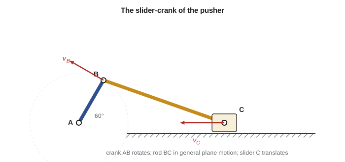
The program below tabulates the slider position and velocity round a full revolution, with the crank turning counterclockwise at 20 rad/s, and checks the hand-derived derivative against a numerical one. It also finds the maximum slider speed and the stroke, which equals twice the crank length.
# Slider-crank pusher: crank r = 0.10 m turning at 20 rad/s CCW,
# connecting rod L = 0.30 m, slider on the line through the crank pivot.
# Absolute motion analysis: write x_C(theta), then differentiate.
import math

r, L, w = 0.10, 0.30, 20.0

def x_C(th):
    return r * math.cos(th) + math.sqrt(L**2 - (r * math.sin(th))**2)

def v_C(th):
    # dx/dt = (dx/dtheta) * omega, differentiated by hand
    s, c = math.sin(th), math.cos(th)
    return (-r * s - r * r * s * c / math.sqrt(L**2 - (r * s)**2)) * w

print(" theta   x_C (m)   v_C (m/s)   v_C numerical")
h = 1e-6
for deg in range(0, 361, 30):
    th = math.radians(deg)
    num = (x_C(th + h) - x_C(th - h)) / (2 * h) * w
    print(f"{deg:5d}   {x_C(th):7.4f}   {round(v_C(th), 4) + 0.0:9.4f}   {round(num, 4) + 0.0:9.4f}")

best = max(range(0, 360), key=lambda d: abs(v_C(math.radians(d))))
print(f"largest slider speed {abs(v_C(math.radians(best))):.3f} m/s near theta = {best} deg")
print(f"stroke = {x_C(0) - x_C(math.pi):.3f} m") theta x_C (m) v_C (m/s) v_C numerical
0 0.4000 0.0000 0.0000
30 0.3824 -1.2928 -1.2928
60 0.3372 -2.0336 -2.0336
90 0.2828 -2.0000 -2.0000
120 0.2372 -1.4305 -1.4305
150 0.2092 -0.7072 -0.7072
180 0.2000 0.0000 0.0000
210 0.2092 0.7072 0.7072
240 0.2372 1.4305 1.4305
270 0.2828 2.0000 2.0000
300 0.3372 2.0336 2.0336
330 0.3824 1.2928 1.2928
360 0.4000 0.0000 0.0000
largest slider speed 2.109 m/s near theta = 73 deg
stroke = 0.200 mTwo features stand out. The slider speed is zero at the ends of the stroke, at 0° and 180°, as it must be when the slider reverses. And the motion is not symmetric: the greatest speed, about 2.11 m/s, occurs near 73°, not at 90°, because the connecting rod's angle distorts the motion. The shorter the rod relative to the crank, the stronger the distortion. Engine designers care about this because it creates the second-order shaking forces that balance shafts are fitted to cancel.
General plane motion: relative velocity analysis
Absolute motion analysis works well when the geometry gives a tidy formula. For more complicated linkages, it is easier to use relative motion. In Lesson 3, \(\mathbf{v}_B = \mathbf{v}_A + \mathbf{v}_{B/A}\). For two points \(A\) and \(B\) on the same rigid body, the distance between them cannot change, so the only possible relative motion of \(B\) as seen from a translating observer at \(A\) is a rotation about \(A\). The relative velocity is therefore \(\boldsymbol{\omega}\times\mathbf{r}_{B/A}\), perpendicular to the line \(AB\) with magnitude \(\omega\,AB\):
This equation says that general plane motion can always be viewed as a translation with a reference point plus a rotation about that point. It is a vector equation in the plane, so it gives two scalar equations and can solve for two unknowns: typically the angular velocity of one link and the speed of a point whose direction of motion is known.
Worked problem
Velocity of the pusher slider by relative velocity
For the slider-crank pusher with \(r = 0.10 \text{ m}\), \(L = 0.30 \text{ m}\) and the crank at 60° turning counterclockwise at 20 rad/s, find the angular velocity of the connecting rod and the velocity of the slider using the relative velocity equation.
Show solution
- Positions, with \(A\) at the origin: \(\mathbf{r}_B = 0.05\,\mathbf{i} + 0.0866\,\mathbf{j}\). The slider lies on the \(x\) axis at \(x_C = 0.05 + \sqrt{0.30^2 - 0.0866^2} = 0.3372 \text{ m}\), so \(\mathbf{r}_{C/B} = 0.2872\,\mathbf{i} - 0.0866\,\mathbf{j}\).
- Crank pin: \(\mathbf{v}_B = 20\mathbf{k}\times(0.05\,\mathbf{i} + 0.0866\,\mathbf{j}) = -1.732\,\mathbf{i} + 1.000\,\mathbf{j} \text{ m/s}\).
- Slider: \(\mathbf{v}_C = v_C\,\mathbf{i}\) (it moves horizontally). Rod: \(\boldsymbol{\omega}_{BC} = \omega_{BC}\mathbf{k}\).
- \[v_C\,\mathbf{i} = (-1.732 + 0.0866\,\omega_{BC})\,\mathbf{i} + (1.000 + 0.2872\,\omega_{BC})\,\mathbf{j}\]
- The \(\mathbf{j}\) components give \(\omega_{BC} = -3.48 \text{ rad/s}\) (clockwise). The \(\mathbf{i}\) components then give \(v_C = -1.732 + 0.0866(-3.48) = -2.03 \text{ m/s}\).
Answer: The rod turns clockwise at 3.48 rad/s and the slider moves left at 2.03 m/s, matching the program's value at 60°.
The relative velocity method extends naturally to four-bar linkages, robot arms and any chain of links: start from a point whose velocity is known, step across each link with \(\boldsymbol{\omega}\times\mathbf{r}\), and use the known directions of motion at sliders and pivots to close the equations. Lesson 9 adds two refinements: a graphical shortcut for velocities, the instantaneous centre, and the corresponding relation for accelerations.
Common mistakes
MistakeUsing revolutions per minute in ω = v/r.
InsteadConvert to radians per second: multiply rev/min by 2π/60.
MistakeGiving each point of a rotating body its own angular velocity.
InsteadA rigid body has one angular velocity; every line in it turns at the same rate.
MistakeTreating the belt as having the drum's normal acceleration.
InsteadThe belt moves along a tangent; its acceleration is the drum's tangential acceleration.
MistakeAssuming the slider of a slider-crank is fastest at 90°.
InsteadThe rod's angle shifts the peak; find it from the motion equation.
MistakeDrawing the relative velocity of B about A along the line AB.
InsteadIt is perpendicular to AB, since the distance AB cannot change.
Summary and key terms
- Planar rigid-body motion is translation, rotation about a fixed axis, or general plane motion.
- θ, ω and α obey the same relations as s, v and a; use radians.
- For fixed-axis rotation, v = ωr, a_t = αr and a_n = ω²r.
- Meshing gears and non-slipping belts share pitch-line velocity and tangential acceleration.
- Absolute motion analysis writes a position in terms of one angle and differentiates.
- Relative velocity: v_B = v_A + ω × r_B/A for two points on one rigid body.
- General plane motion is a translation with a reference point plus a rotation about it.
- Rigid body
- A body in which distances between points never change.
- Translation
- Motion in which every line in the body stays parallel to itself.
- Fixed-axis rotation
- Motion in which every point moves on a circle about a fixed axis.
- General plane motion
- Planar motion combining translation and rotation.
- Angular velocity
- The rate of change of a body's angular position.
- Angular acceleration
- The rate of change of angular velocity.
- Slider-crank
- A mechanism that converts rotation of a crank into straight-line motion of a slider.
- Absolute motion analysis
- Finding velocities by differentiating a geometric position relation.
Practice problems
Work each problem on paper first, then reveal the answer to check.
A fan speeds up from 600 to 1,200 rev/min in 4 s. What is its angular acceleration?
Show answer
(125.7 - 62.8)/4 = 15.7 rad/s².
A point 0.15 m from the axis of a wheel turning at 40 rad/s: what is its speed and normal acceleration?
Show answer
6 m/s and 240 m/s².
A 20-tooth pinion drives a 60-tooth gear. The pinion turns at 900 rev/min. How fast does the gear turn?
Show answer
300 rev/min, in the opposite sense.
What is the slider velocity of the pusher at θ = 90°, and why is the rod's angular velocity zero there?
Show answer
-2.00 m/s; at 90° the crank pin's velocity is horizontal, so the rod translates momentarily.
Change L in the program to 0.20 m. What happens to the peak slider speed and where it occurs?
Show answer
It rises and moves further from 90°, because a shorter rod distorts the motion more.
Why must angles be in radians in v = ωr?
Show answer
The formula comes from arc length s = rθ, which holds only for θ in radians.
Lesson quiz · 5 questions
Score 60% or more to complete this lesson.
Create a free account to save your progress, take quizzes and earn a certificate.