
MEC-210 · Lesson 9 of 12 · 27 min
Instantaneous centres and relative acceleration
Lesson 8 found velocities in a linkage by writing \(\mathbf{v}_B = \mathbf{v}_A + \boldsymbol{\omega}\times\mathbf{r}_{B/A}\) and solving the components. This lesson adds two tools. The instantaneous centre of zero velocity is a geometric shortcut that often finds velocities in a few lines, and it builds a feel for how a mechanism moves that equations alone do not give. The relative acceleration equation extends the analysis to accelerations, which is what you need for forces: the second law cares about accelerations, not velocities. The lesson finishes with a short look at motion relative to rotating axes, which explains where the Coriolis acceleration of Lesson 2 comes from in rigid-body terms.
The instantaneous centre of zero velocity
At any instant, a rigid body in general plane motion has velocities that look exactly as if the body were rotating about some point, the instantaneous centre of zero velocity, often written IC. That point may lie on the body or off it, in empty space beside the mechanism. At that instant its velocity is zero, and every point on the body moves at right angles to the line joining it to the IC, with a speed equal to \(\omega\) times its distance from the IC:
The IC exists because the relative velocity equation can be applied with any reference point. If we pick as the reference the one point whose velocity happens to be zero, the translation part vanishes and only rotation is left. As the body moves, the IC moves too, which is why it is called instantaneous: it is the centre of rotation only for that instant.
Locating the IC uses the fact that each point's velocity is perpendicular to the line from the IC. Three cases cover almost every problem.
- If the directions of the velocities of two points are known, draw lines through each point perpendicular to its velocity. The IC is where the lines cross.
- If the velocities of two points are parallel and perpendicular to the line joining them, the IC lies on that line, located by proportion from the two speeds. If the speeds are equal, the IC is infinitely far away and the body is translating at that instant, with \(\omega = 0\).
- A wheel that rolls without slipping has its IC at the contact point, because the contact point and the ground have the same velocity, zero.
Worked problem
The pusher by instantaneous centre
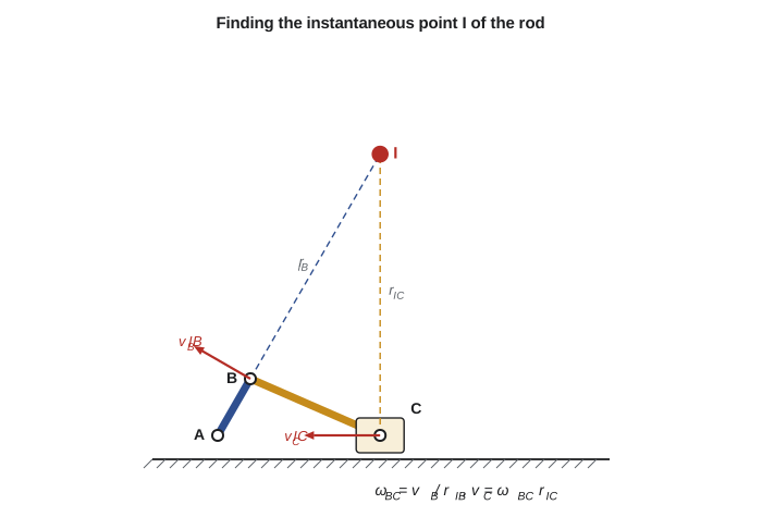
For the slider-crank pusher of Lesson 8, with \(r = 0.10 \text{ m}\), \(L = 0.30 \text{ m}\) and the crank at 60° turning counterclockwise at 20 rad/s, find the rod's angular velocity and the slider's velocity using the instantaneous centre.
Show solution
- The crank pin \(B\) moves perpendicular to the crank, at \(v_B = \omega r = 20(0.10) = 2.0 \text{ m/s}\). The perpendicular to \(\mathbf{v}_B\) through \(B\) is the line of the crank itself, extended.
- The slider \(C\) moves horizontally, so the perpendicular through \(C\) is vertical, along \(x = 0.3372 \text{ m}\).
- The crank line is \(y = x\tan 60^\circ\), which meets \(x = 0.3372\) at \(y = 0.584 \text{ m}\). So the IC of the rod is at \(I = (0.337, 0.584)\).
- Distances: \(IB = \sqrt{(0.337 - 0.050)^2 + (0.584 - 0.087)^2} = 0.574 \text{ m}\) and \(IC = 0.584 \text{ m}\).
- \[\omega_{BC} = \frac{v_B}{IB} = \frac{2.0}{0.574} = 3.48 \text{ rad/s} \qquad v_C = \omega_{BC}\,IC = 3.48(0.584) = 2.03 \text{ m/s}\]
- Directions: \(B\) moves up and to the left, so the rod turns clockwise about \(I\), and \(C\), directly below \(I\), moves to the left.
Answer: The rod turns clockwise at 3.48 rad/s and the slider moves left at 2.03 m/s, agreeing with both methods of Lesson 8.
The IC method also explains the special positions of the mechanism at a glance. At 90°, the crank is vertical, the perpendicular to \(\mathbf{v}_B\) is horizontal and never meets the vertical through \(C\): the IC is at infinity, the rod is translating, and the slider moves at exactly the crank pin speed, 2.0 m/s. At 0° and 180°, the crank and rod are in line, the IC of the rod coincides with \(C\), and the slider is momentarily at rest. These are the dead-centre positions.
Rolling without slipping
A wheel of radius \(r\) rolling without slipping on a flat surface has its IC at the contact point. Its centre moves at \(v_G = \omega r\), and since that holds at every instant, differentiating gives \(a_G = \alpha r\) for the centre's acceleration along the surface. The top of the wheel, twice as far from the IC as the centre, moves at \(2v_G\). This is why the top of a bicycle tyre looks blurred in photographs while the bottom looks sharp.
Worked problem
A shuttle wheel slowing down
A shuttle wheel of radius 75 mm rolls without slipping. At an instant when the shuttle moves at 2.0 m/s and is slowing at 1.5 m/s², find the wheel's angular velocity and angular acceleration, the velocity of the top of the wheel, and the acceleration of the contact point.
Show solution
- \(\omega = v_G/r = 2.0/0.075 = 26.7 \text{ rad/s}\); \(\alpha = a_G/r = 1.5/0.075 = 20.0 \text{ rad/s}^2\), opposing the rotation.
- Top of the wheel: \(v = \omega(2r) = 26.7(0.15) = 4.0 \text{ m/s}\), forward.
- Contact point: use \(\mathbf{a}_P = \mathbf{a}_G + \boldsymbol{\alpha}\times\mathbf{r}_{P/G} - \omega^2\mathbf{r}_{P/G}\). The tangential parts cancel (rolling), leaving \(\omega^2 r = (26.7)^2(0.075) = 53.3 \text{ m/s}^2\) directed up toward the centre.
Answer: The contact point has zero velocity but a large acceleration toward the wheel centre. The IC is a point of zero velocity, not zero acceleration, so it must never be used to find accelerations.
That warning is the single most important limitation of the instantaneous centre. It gives velocities correctly at an instant, but because the IC itself moves from instant to instant, treating it as a fixed pivot for accelerations gives wrong answers. For accelerations, go back to the relative acceleration equation.
Relative acceleration
Differentiating the relative velocity equation for two points on the same rigid body gives
The relative acceleration of \(B\) about \(A\) has two parts, exactly like a point on a body rotating about a fixed axis through \(A\): a tangential part \(\alpha\,AB\), perpendicular to \(AB\), and a normal part \(\omega^2 AB\), directed from \(B\) toward \(A\). The angular velocity \(\omega\) is already known from the velocity analysis, so the normal part is fully known. The unknowns are usually the angular acceleration \(\alpha\) of a link and the magnitude of the acceleration of a point whose path is known, such as a slider. The vector equation gives two scalar equations, enough for both.
A practical order of work: always complete the velocity analysis first, because the accelerations need the angular velocities. Then write the acceleration equation link by link, starting from a point whose acceleration is known (a fixed pivot, or a crank pin on a crank turning at a known rate).
Worked problem
Acceleration of the pusher slider
For the pusher at a crank angle of 60°, with the crank turning at a constant 20 rad/s counterclockwise, find the angular acceleration of the rod and the acceleration of the slider. From the velocity analysis, \(\omega_{BC} = -3.48 \text{ rad/s}\).
Show solution
- Crank pin: the crank turns at constant speed, so only the normal part acts: \(\mathbf{a}_B = -\omega^2\mathbf{r}_B = -400(0.05\,\mathbf{i} + 0.0866\,\mathbf{j}) = -20.0\,\mathbf{i} - 34.6\,\mathbf{j} \text{ m/s}^2\).
- Rod: \(\mathbf{r}_{C/B} = 0.2872\,\mathbf{i} - 0.0866\,\mathbf{j}\), \(\omega_{BC}^2 = 12.12\). Unknowns: \(\alpha_{BC}\) and \(a_C\) (horizontal).
- \[a_C\,\mathbf{i} = (-20.0 + 0.0866\,\alpha_{BC} - 3.48)\,\mathbf{i} + (-34.6 + 0.2872\,\alpha_{BC} + 1.05)\,\mathbf{j}\]
- The \(\mathbf{j}\) components give \(\alpha_{BC} = 117 \text{ rad/s}^2\) (counterclockwise).
- The \(\mathbf{i}\) components give \(a_C = -23.5 + 0.0866(117) = -13.4 \text{ m/s}^2\).
Answer: The slider accelerates at 13.4 m/s² to the left at this instant, while moving left at 2.03 m/s: it is still speeding up. The rod's angular acceleration is 117 rad/s² counterclockwise, slowing its clockwise rotation.
The program below repeats the velocity and acceleration analysis round half a revolution and checks the slider acceleration against a numerical second derivative of the position formula from Lesson 8. It also confirms, by an internal check, that the rod's angular velocity agrees with the instantaneous centre construction at every angle where the IC is at a finite distance.
# Pusher slider-crank (r = 0.10 m, L = 0.30 m, crank at a constant
# 20 rad/s CCW). Velocities from the instantaneous centre of the rod,
# accelerations from the relative-acceleration equation, checked against
# a numerical second derivative of the slider position.
import math

r, L, w = 0.10, 0.30, 20.0

def xC(th):
    return r * math.cos(th) + math.sqrt(L**2 - (r * math.sin(th))**2)

def analyse(th):
    B = (r * math.cos(th), r * math.sin(th))
    C = (xC(th), 0.0)
    rCB = (C[0] - B[0], C[1] - B[1])
    vB = (-w * B[1], w * B[0])
    # Rod angular velocity from the j-component of vC = vB + wBC k x rCB
    wBC = -vB[1] / rCB[0]
    # Check with the instantaneous centre: crank line meets vertical through C
    if abs(math.cos(th)) > 1e-9:
        I = (C[0], C[0] * math.tan(th))
        IB = math.hypot(B[0] - I[0], B[1] - I[1])
        assert abs(abs(wBC) - r * w / IB) < 1e-9
    vC = vB[0] - wBC * rCB[1]
    # Accelerations: aB = -w^2 rB (alpha_crank = 0)
    aB = (-w * w * B[0], -w * w * B[1])
    # aC = aB + aBC k x rCB - wBC^2 rCB, with aC purely along x
    aBC = -(aB[1] - wBC**2 * rCB[1]) / rCB[0]
    aC = aB[0] - aBC * rCB[1] - wBC**2 * rCB[0]
    return wBC, vC, aBC, aC

h = 1e-4
print(" theta  w_BC(rad/s)  v_C(m/s)  alpha_BC(rad/s^2)  a_C(m/s^2)  a_C numerical")
for deg in (0, 30, 60, 90, 120, 150, 180):
    th = math.radians(deg)
    wBC, vC, aBC, aC = analyse(th)
    num = (xC(th + h) - 2 * xC(th) + xC(th - h)) / h**2 * w * w
print(f"{deg:5d} {round(wBC, 3) + 0.0:10.3f} {round(vC, 3) + 0.0:8.3f} {round(aBC, 1) + 0.0:15.1f} {aC:10.2f} {num:10.2f}") theta w_BC(rad/s) v_C(m/s) alpha_BC(rad/s^2) a_C(m/s^2) a_C numerical
0 -6.667 0.000 0.0 -53.33 -53.33
30 -5.855 -1.293 61.8 -41.69 -41.69
60 -3.482 -2.034 116.9 -13.35 -13.35
90 0.000 -2.000 141.4 14.14 14.14
120 3.482 -1.431 116.9 26.65 26.65
150 5.855 -0.707 61.8 27.59 27.59
180 6.667 0.000 0.0 26.67 26.67The table shows something a designer needs to know. The slider's acceleration is largest in magnitude at 0°, the outer dead centre, where it is \(r\omega^2(1 + r/L) = 53.3 \text{ m/s}^2\), and smaller at 180°, the inner dead centre, where it is \(r\omega^2(1 - r/L) = 26.7 \text{ m/s}^2\). The asymmetry comes from the finite length of the rod. The force needed to accelerate the slider and whatever it pushes peaks at the outer dead centre, so that is where the connecting rod, its pins and the crank bearings see their highest inertia loads. Lesson 10 turns these accelerations into forces.
Motion relative to rotating axes
Sometimes the most natural description of a mechanism uses a reference frame that rotates: a pin sliding in a slot of a rotating arm, a block moving along a turning robot link, a quick-return mechanism. For a point \(B\) whose motion is described relative to axes attached to a body rotating at \(\boldsymbol{\Omega}\) about a point \(A\), the velocity and acceleration are
The subscript rel means as measured by an observer riding on the rotating axes. The first three acceleration terms are those of a point fixed to the rotating body; the last is the acceleration seen by the rotating observer; and the fourth, \(2\boldsymbol{\Omega}\times\mathbf{v}_{rel}\), is the Coriolis acceleration. For a point moving straight out along a rotating arm, these terms reduce exactly to the polar-coordinate result of Lesson 2, with the Coriolis term \(2\dot r\dot\theta\). The Coriolis acceleration is not a correction or an approximation; it is a real acceleration in the ground frame, and the slot or guide must supply the force to produce it.
| Tool | Finds | Watch out for |
|---|---|---|
| Instantaneous centre | Velocities and angular velocities at an instant | Never use it for accelerations |
| Relative velocity equation | Velocities, two unknowns per vector equation | Relative velocity is perpendicular to the line joining the points |
| Relative acceleration equation | Angular accelerations and point accelerations | Needs ω from the velocity analysis first; include the ω² term |
| Rotating axes | Sliding contacts on rotating links | Include the Coriolis term 2Ω × v_rel |
Common mistakes
MistakeUsing the instantaneous centre to find accelerations.
InsteadThe IC has zero velocity but generally not zero acceleration; use the relative acceleration equation.
MistakeLeaving out the -ω²r term in the relative acceleration equation.
InsteadBoth the tangential and normal relative terms are needed.
MistakeStarting the acceleration analysis before finding the angular velocities.
InsteadDo the velocity analysis first; the normal terms need ω.
MistakeAssuming the contact point of a rolling wheel has zero acceleration.
InsteadIt accelerates toward the centre at ω²r.
MistakeIgnoring the Coriolis term for a slider on a rotating link.
InsteadInclude 2Ω × v_rel whenever there is relative motion in a rotating frame.
Summary and key terms
- Every body in plane motion has an instantaneous centre of zero velocity at each instant.
- Find the IC where perpendiculars to two known velocity directions intersect.
- A rolling wheel's IC is the contact point; v_G = ωr and a_G = αr.
- The IC gives velocities only, never accelerations.
- Relative acceleration: a_B = a_A + α × r_B/A - ω² r_B/A.
- Slider-crank inertia loads peak at the outer dead centre, at rω²(1 + r/L).
- In rotating frames, the Coriolis term 2Ω × v_rel is a real acceleration.
- Instantaneous centre
- The point about which a body appears to rotate at an instant; its velocity is zero.
- Dead centre
- A position where the crank and connecting rod are in line and the slider is momentarily at rest.
- Rolling without slipping
- Rolling in which the contact point has zero velocity relative to the surface.
- Relative acceleration
- The acceleration of one point as seen from another point on the same body.
- Normal relative acceleration
- The ω²r component directed from one point toward the other.
- Tangential relative acceleration
- The αr component perpendicular to the line joining the points.
- Rotating axes
- A reference frame that turns with a body.
- Coriolis acceleration
- The 2Ω × v_rel term from relative motion in a rotating frame.
Practice problems
Work each problem on paper first, then reveal the answer to check.
Where is the IC of a ladder sliding down a wall, with its top on the wall and its foot on the floor?
Show answer
At the intersection of the horizontal through the top and the vertical through the foot.
A wheel of radius 0.3 m rolls at 6 m/s. What is the speed of a point on the rim level with the centre?
Show answer
ω = 20 rad/s; distance from IC is 0.3√2 = 0.424 m, so 8.49 m/s.
For the pusher at 90°, what are the rod's angular velocity and the slider's velocity?
Show answer
ω_BC = 0 (the rod translates) and v_C = 2.0 m/s to the left.
What is the slider acceleration of the pusher at 0° if the crank speed doubles to 40 rad/s?
Show answer
Four times as large: 213 m/s².
In the program, change L to 0.50 m. What happens to the difference between the accelerations at 0° and 180°?
Show answer
It shrinks, because r/L falls from 1/3 to 1/5.
A pin slides outward at 0.5 m/s along a slot in an arm turning at 4 rad/s. What is its Coriolis acceleration?
Show answer
2 x 4 x 0.5 = 4 m/s², perpendicular to the slot.
Lesson quiz · 5 questions
Score 60% or more to complete this lesson.
Create a free account to save your progress, take quizzes and earn a certificate.