
ROB-330 · Lesson 7 of 12 · 31 min
Visual odometry and structure from motion
A camera moving through the world sees the scene shift between frames, and that shift encodes both how the camera moved and where the scene points are. Visual odometry (VO) uses it to estimate the camera's motion frame by frame, like wheel odometry but without slipping wheels; structure from motion (SfM) recovers the camera poses and the 3-D structure together from a collection of images. VO runs on drones, planetary rovers (NASA's Mars rovers have used it since 2004), legged robots and phones, and it is the front end of the visual SLAM systems in ROB-340. This lesson assembles the pieces from lessons 2 to 6 into a working pipeline: matching, two-view motion from the essential matrix, triangulation, tracking against a growing map, and refinement by bundle adjustment.
The visual odometry pipeline
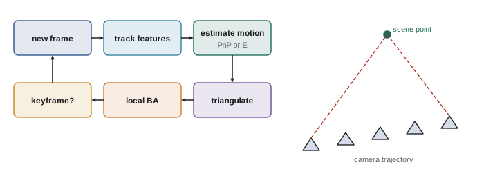
A typical feature-based monocular VO system repeats the same loop for each new frame.
1. Detect features (for example ORB or Shi–Tomasi corners) and match or track them from the previous frame. Tracking with the Lucas–Kanade optical-flow method, which follows each corner by minimizing brightness differences in a small window, is common at high frame rates because motion between frames is small.
2. Estimate the relative motion: with no map yet, from the essential matrix (five-point RANSAC); once 3-D points exist, from 2-D to 3-D matches with perspective-n-point (PnP, lesson 11), which is faster and more stable.
3. Triangulate new points seen in two or more frames to extend the map.
4. Periodically refine recent poses and points with local bundle adjustment.
5. Select keyframes: rather than keeping every frame, keep one when the camera has moved enough, or enough features have been lost, to add new information.
Direct methods such as DSO and semi-direct methods such as SVO skip explicit feature matching and instead minimize photometric error, the brightness difference between images warped by the estimated motion and depth. They use more of the image, including edges and weak texture, but need photometric calibration and are more sensitive to exposure changes. Feature-based methods such as ORB-SLAM's tracking front end are more tolerant of large motions and lighting changes.
Motion from two views
With calibrated cameras, the five-point algorithm inside RANSAC gives the essential matrix between two frames, and decomposing it gives the rotation R and the direction of the translation t, as lesson 6 explained. Two practical points matter. First, the estimate is poor when the translation is small relative to the scene depth, because the views then differ almost only by rotation and the translation direction is barely observable. VO systems wait for enough parallax, often measured as the median angle between corresponding rays, before initializing. Second, when the scene is nearly planar, the essential matrix becomes poorly determined, and a homography fits better; ORB-SLAM computes both and picks the model that explains the matches best.
import numpy as np
rng = np.random.default_rng(11)

def skew(t):
    return np.array([[0, -t[2], t[1]], [t[2], 0, -t[0]], [-t[1], t[0], 0]])

def rotz(a):
    c, s = np.cos(a), np.sin(a)
    return np.array([[c, -s, 0], [s, c, 0], [0, 0, 1]])

def roty(a):
    c, s = np.cos(a), np.sin(a)
    return np.array([[c, 0, s], [0, 1, 0], [-s, 0, c]])

# scene points 3-8 m ahead of camera 1; camera 2 moved and turned slightly
X = np.column_stack([rng.uniform(-2, 2, 60), rng.uniform(-1, 1, 60), rng.uniform(3, 8, 60)])
R_true = roty(np.deg2rad(5)) @ rotz(np.deg2rad(2))
t_true = np.array([0.5, 0.0, 0.1])                     # m, camera-2 frame
x1 = X / X[:, 2:]                                      # normalized coordinates
X2 = (R_true @ X.T).T + t_true
x2 = X2 / X2[:, 2:]
x1[:, :2] += rng.normal(0, 0.0005, (60, 2))           # about 0.5 px noise at f = 1000
x2[:, :2] += rng.normal(0, 0.0005, (60, 2))

# eight-point algorithm on all points, then enforce two equal singular values
A = np.array([np.kron(b, a) for a, b in zip(x1, x2)])
E = np.linalg.svd(A)[2][-1].reshape(3, 3)
U, S, Vt = np.linalg.svd(E)
E = U @ np.diag([1, 1, 0]) @ Vt

# decompose E into four candidates; keep the one with points in front of both cameras
U, _, Vt = np.linalg.svd(E)
if np.linalg.det(U) < 0: U = -U
if np.linalg.det(Vt) < 0: Vt = -Vt
Wm = np.array([[0, -1, 0], [1, 0, 0], [0, 0, 1]])
best = None
for R in (U @ Wm @ Vt, U @ Wm.T @ Vt):
    for t in (U[:, 2], -U[:, 2]):
        good = 0
        for a, b in zip(x1, x2):
            # solve z1 * R a + t = z2 * b for depths z1, z2 by least squares
            M = np.column_stack([R @ a, -b])
            z = np.linalg.lstsq(M, -t, rcond=None)[0]
            good += (z[0] > 0) and (z[1] > 0)
        if best is None or good > best[0]:
            best = (good, R, t)
good, R_est, t_est = best

ang = np.degrees(np.arccos(np.clip((np.trace(R_est.T @ R_true) - 1) / 2, -1, 1)))
tdir = np.degrees(np.arccos(abs(t_est @ t_true) / np.linalg.norm(t_true)))
print("points in front of both cameras: %d of 60" % good)
print("rotation error: %.3f deg" % ang)
print("translation direction error: %.2f deg" % tdir)
print("estimated |t| = %.2f (unit length: true scale %.2f m is unobservable)" % (np.linalg.norm(t_est), np.linalg.norm(t_true)))points in front of both cameras: 60 of 60 rotation error: 0.225 deg translation direction error: 1.12 deg estimated |t| = 1.00 (unit length: true scale 0.51 m is unobservable)
Triangulation
Given the two camera poses and a matched pair of image points, the 3-D point lies where the two rays meet. With noise they never quite meet, so triangulation finds the point that best fits both. The linear method stacks the two projection equations into a small homogeneous system and solves it by SVD; the midpoint method takes the midpoint of the shortest segment between the rays; the optimal method minimizes reprojection error in both images. Triangulation accuracy depends on the angle between the rays, the parallax angle: depth uncertainty grows sharply as that angle shrinks, which is the same geometry as stereo depth error in lesson 6, with the distance travelled between frames acting as the baseline.
Worked problem
Triangulation from a sideways move
A camera with f = 800 px moves 0.40 m sideways without rotating. A feature appears at u = 452 in the first image and u = 372 in the second (principal point 320). How far away is it, and what is the parallax angle?
Show solution
- This is a stereo pair with baseline 0.40 m and disparity \( 452 - 372 = 80 \) px.
- Depth: \( Z = fB/d = 800 \times 0.40/80 = 4.0 \) m.
- Parallax angle: about \( B/Z = 0.40/4.0 = 0.10 \) rad, or 5.7°.
Answer: 4.0 m, with a comfortable 5.7° of parallax. Had the camera moved only 4 cm, the parallax would be 0.57° and the depth estimate ten times less precise.
Scale and drift
A single camera cannot measure absolute scale: shrink the whole scene and the camera's motion by the same factor and every image is unchanged. Monocular VO therefore fixes the scale arbitrarily at initialization (say, the first translation has unit length) and carries it forward. Errors in triangulation then let the scale wander slowly, scale drift, so a monocular trajectory may be shaped correctly but grow or shrink over a long run. Scale is anchored with extra information: a stereo camera or depth sensor, wheel odometry, an IMU (visual-inertial odometry estimates scale from accelerometer readings, and is the norm on drones and phones), a known object size or the known height of the camera above a flat floor.
All odometry also drifts in position and heading, because each frame's small error is added to every later pose. Good stereo or visual-inertial odometry typically drifts about 0.5 % to 2 % of the distance travelled, depending on the environment and motion. Correcting that drift needs recognizing previously visited places and closing loops, which is the job of SLAM in ROB-340.
Worked problem
Accumulated drift
A warehouse robot uses visual-inertial odometry with 1 % drift. After a 250 m patrol, how large might its position error be? How does that compare with a 0.3 m docking tolerance?
Show solution
- Drift: \( 0.01 \times 250 = 2.5 \) m.
- Compared with the 0.3 m tolerance: more than eight times too large.
Answer: About 2.5 m, so odometry alone cannot dock the robot. It needs loop closure, a map with localization, or a fiducial at the dock to reset the error.
Worked problem
Recovering scale from camera height
A monocular VO system on a ground robot reconstructs the floor plane 0.62 units below the camera, while the camera is actually mounted 0.31 m above the floor. The VO reports a translation of 4.2 units. How far did the robot really move?
Show solution
- Scale factor: \( 0.31 \text{ m}/0.62 \text{ units} = 0.5 \) m per unit.
- Real distance: \( 4.2 \times 0.5 = 2.1 \) m.
Answer: 2.1 m. Re-estimating the floor plane every few frames keeps the scale anchored as it drifts.
Bundle adjustment
VO's frame-to-frame estimates are locally consistent but not optimal. Bundle adjustment (BA) refines all camera poses and 3-D points together by minimizing the total reprojection error over every observation, the same objective as calibration in lesson 3 but with the cameras' poses and the points as unknowns:
where ρ is a robust loss to limit the influence of remaining outliers. The name refers to the bundles of rays from each camera, adjusted until they meet the points as well as possible. The problem is large (thousands of points and hundreds of cameras) but very sparse, because each point is seen by only a few cameras, and solvers such as Ceres, g2o and GTSAM exploit that sparsity with the Schur complement trick to eliminate the points and solve a small system for the cameras first. This is the same factor-graph optimization introduced in ROB-310, with reprojection factors. VO systems run local BA over a sliding window of recent keyframes in real time; offline SfM pipelines such as COLMAP run global BA over thousands of photos to build 3-D models.
Worked problem
Size of a bundle adjustment problem
A local BA window has 10 keyframes and 2,000 points, each point seen on average in 4 keyframes. How many unknowns and residuals does it have?
Show solution
- Unknowns: \( 10 \times 6 = 60 \) pose parameters plus \( 2000 \times 3 = 6000 \) point coordinates: 6,060.
- Observations: \( 2000 \times 4 = 8000 \), each giving 2 residuals: 16,000.
- After the Schur complement removes the points, the reduced camera system is only 60 × 60.
Answer: About 6,060 unknowns and 16,000 residuals, but the sparse structure reduces the core solve to a 60 × 60 system, which is why local BA runs at frame rate.
Where visual odometry struggles
VO fails in predictable situations, and a robot should detect them rather than trust a bad estimate. Textureless surfaces such as white walls and smooth floors give too few features. Fast motion causes blur and large inter-frame displacement. Moving objects such as people, forklifts and doors violate the static-scene assumption unless rejected as outliers. Sudden lighting changes and auto-exposure jumps break brightness constancy for direct methods. Pure rotation gives no parallax for triangulation. Low light raises noise. The standard mitigations are an IMU to bridge short failures, global-shutter cameras with short exposures, a wider field of view, fixed exposure or photometric calibration, and monitoring of the number of tracked features and inliers to flag degraded tracking.
Common mistakes
MistakeInitializing monocular VO from two frames with very little translation
InsteadWait for enough parallax, measured by the angle between corresponding rays.
MistakeReporting monocular VO distances in metres without a scale source
InsteadAnchor scale with stereo, an IMU, wheel odometry, camera height or a known object.
MistakeTreating odometry drift as negligible on long runs
InsteadExpect error proportional to distance and correct it with loop closure or landmarks.
MistakeRunning bundle adjustment with a plain squared loss on raw matches
InsteadUse a robust loss and reject outliers first.
MistakeIgnoring moving people and vehicles in the scene
InsteadReject them as RANSAC outliers or mask them with a detector.
Summary and key terms
- Visual odometry estimates camera motion frame by frame from tracked or matched features; SfM recovers poses and structure together.
- Two-view motion comes from the essential matrix with five-point RANSAC; once a map exists, PnP is used.
- Decomposing E gives four candidates; the cheirality check keeps the one with points in front of both cameras.
- Triangulation accuracy depends on the parallax angle, like stereo with the motion as baseline.
- Monocular VO cannot observe scale, which drifts unless anchored by other sensors or known geometry.
- All odometry drifts with distance travelled, typically around 1 %, and needs loop closure to correct.
- Bundle adjustment jointly refines poses and points by robust, sparse minimization of reprojection error.
- Visual odometry
- Estimating a camera's motion incrementally from successive images.
- Structure from motion
- Recovering camera poses and 3-D structure from a set of images.
- Optical flow
- The apparent motion of image brightness patterns between frames.
- Keyframe
- A selected frame kept for mapping and optimization.
- Triangulation
- Computing a 3-D point from its images in two or more known views.
- Parallax angle
- The angle between the rays to a point from two camera positions.
- Cheirality
- The requirement that reconstructed points lie in front of the cameras.
- Scale drift
- Slow change in the unobservable scale of a monocular reconstruction.
- Bundle adjustment
- Joint optimization of camera poses and 3-D points by minimizing reprojection error.
- Visual-inertial odometry
- Odometry combining a camera with an IMU, which also provides metric scale.
Practice problems
Work each problem on paper first, then reveal the answer to check.
Name a common way to track corners between consecutive frames.
Show answer
Lucas–Kanade optical flow.
How many solutions does decomposing the essential matrix give?
Show answer
Four.
B = 0.2 m, f = 500 px, d = 25 px: what is the depth?
Show answer
4 m.
Why can't monocular VO measure absolute scale?
Show answer
Scaling the scene and motion together leaves the images unchanged.
A robot drives 80 m with 1.5 % drift. What position error results?
Show answer
About 1.2 m.
Give two sensors that can anchor monocular scale.
Show answer
An IMU, wheel odometry, a stereo camera or a depth sensor.
What does bundle adjustment minimize?
Show answer
Total (robust) reprojection error over all observations.
Which trick makes bundle adjustment efficient?
Show answer
The Schur complement, exploiting sparsity.
When does VO prefer a homography over E?
Show answer
When the scene is nearly planar or motion is nearly pure rotation.
Name two conditions that make VO fail.
Show answer
Textureless scenes, fast motion and blur, moving objects, lighting changes or pure rotation.
Lesson quiz · 5 questions
Score 60% or more to complete this lesson.
Create a free account to save your progress, take quizzes and earn a certificate.